Disassembly
Service Manual 6-31
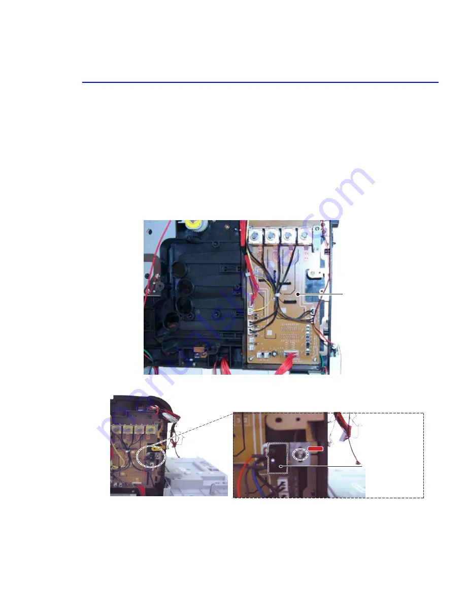
6.4.12 DEVE Drive Board (PL 9.13.20) and
DEVE Cover Open Switch (PL 9.15.36) (Door A Interlock)
Warning
High Voltage! Be sure to follow the steps outlined in Section 1.5.4 when servicing this assembly
1.
Remove the rear cover. (6.4.3)
2.
Remove the main board. (6.4.7b)
3.
Remove the main board shield. (6.4.7b)
4.
Remove the main board bracket, steps 1 and 2 from 6.4.11.
5.
Free the wiring from the black harness guide.
6.
Remove the screw (3-10 silver) from the guide and remove it.
7.
Remove the screw (3-10 silver) and then take out the DEVE cover open S/W.
DEVE
Board
Deve Cover Open S/W
Screw
Summary of Contents for Phaser 6100
Page 1: ...Service Manual X XEROX P h a s e r C o l o r L a s e r P r i n t e r 6100 ...
Page 2: ......
Page 10: ...vi ...
Page 22: ...Reference Information 2 6 ...
Page 28: ...Specifications 3 6 ...
Page 38: ...Summary of Product 4 10 RAM DIMM SPGPm Main Control FLASH MEMORY ENGINE CONTROL ...
Page 44: ...Summary of Product 4 16 ...
Page 66: ...Disassembly 6 10 3 Remove the toner caps and fit them to the inlets as shown below Toner Cap ...
Page 94: ...Disassembly 6 38 6 Disconnect 2 harnesses and remove the laser unit Harness Harness ...
Page 130: ...Maintenance and Diagnostics 7 20 ...
Page 196: ...Parts List 9 42 9 21 Transfer Belt Cam Assembly S18 9 0 8 S8 7 6 5 10 1 2 14 3 12 13 S8 11 4 ...
Page 200: ...Parts List 9 46 ...


