


Theory of Operation
2-7
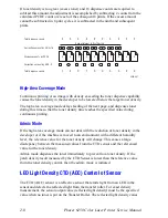
Bias control operates as follows:
1.
The Temperature/Humidity Sensor sets the target values of the drum charging
voltage and biasing DC voltage.
2.
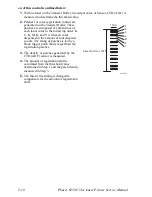
Bias control test patches (see the adjacent figure for
patch configuration) of each of the four toner colors
(yellow, magenta, cyan, and black) are generated and
transferred to the Transfer Roller.
3.
The CTD (ADC) Sensor compares an area on the
Transfer Roller where no toner is present with the test
patches to determine toner density for each of the four
colors.
4.
The density measured in Step 3 is compared with the
target value set in Step 1 and the resulting difference
is used to adjust the drum charging voltage and the
biasing DC voltage for each toner color.
Toner Density Control
Toner density must be kept constant to attain a stable print image. To achieve this
goal, the rate at which toner is dispensed must be adjusted to exactly match the rate at
which it is consumed. There are two systems that work in conjunction to control toner
density: the Pixel Count Dispense Control (PCDC) and the Toner Density Control
(CTD). (The CTD uses data from the ADC sensor, measured as described in the
preceding paragraphs covering bias control.)
PCDC
: The amount of toner consumed in the developing process is calculated by
counting the digital pulses applied to the Laser Unit. The toner motor is then driven
for a period determined by the calculated result to supply toner to the developer,
equivalent to the amount dispensed.
CTD (ADC)
: The toner test patches of each color (yellow, magenta, cyan, and black),
are generated and transferred to the transfer roller as specified in the Bias Control
section. The CTD (ADC) sensor measuers the density of each patch. The printer
adjusts the toner dispense time, which changes the quantity of toner to be dispensed.
This calculation is made separately for each color. The CTD adjustment is made
following completion of printing if either of the following conditions is satisfied:
■
Cumulative print count since power on exceeds 16 pages.
■
When a cleaning cycle is executed during continuous printing.
If either of the preceding control calculations results in an adjustment to the toner
quantity to be dispensed, the result is calculated in terms of number of revolutions of
the Toner Motor. For this description, this value is called the dispense count.
The dispense count calculated as specified above, is implemented over the next 8
prints. If 16 dispense counts are required as a result of low toner density during the
CTD calculation, 2 dispense counts are added during each of the next 8 prints. This is
in addition to any counts added or subtracted during each print as a result of PCDC.
Y
M
C
K
About 11mm
About 57mm
About 12mm
About 3mm
6250-069
Summary of Contents for PHASER 6250
Page 1: ...Service Manual Phaser 6250 701P46430 Color Laser Printer ...
Page 2: ......
Page 40: ...1 16 Phaser 6250 Color Laser Printer Service Manual ...
Page 168: ...3 86 Phaser 6250 Color Laser Printer Service Manual ...
Page 214: ...5 26 Phaser 6250 Color Laser Printer Service Manual ...
Page 226: ...7 4 Phaser 6250 Color Laser Printer Service Manual ...
Page 349: ...Service Parts Disassembly 8 123 8 Repeat Steps 1 7 to remove the lower guide 6250 278 ...
Page 376: ...9 4 Phaser 6250 Color Laser Printer Service Manual Print Engine Parts PL 1 1 Covers 6250 286 ...
Page 380: ...9 8 Phaser 6250 Color Laser Printer Service Manual PL 3 1 Paper Feed I 6250 288 ...
Page 382: ...9 10 Phaser 6250 Color Laser Printer Service Manual PL 3 2 Paper Feed II 6250 289 ...
Page 384: ...9 12 Phaser 6250 Color Laser Printer Service Manual PL 3 3 Paper Feed III 6250 290 ...
Page 386: ...9 14 Phaser 6250 Color Laser Printer Service Manual PL 4 1 Housing Assembly Retard 6250 291 ...
Page 388: ...9 16 Phaser 6250 Color Laser Printer Service Manual PL 5 1 Chute Assembly In 6250 292 ...
Page 390: ...9 18 Phaser 6250 Color Laser Printer Service Manual PL 6 1 Chute Assembly Out 6250 293 ...
Page 393: ...Parts List 9 21 This Page Intentionally Left Blank ...
Page 394: ...9 22 Phaser 6250 Color Laser Printer Service Manual PL 7 1 Chute Assembly Exit 6250 294 ...
Page 398: ...9 26 Phaser 6250 Color Laser Printer Service Manual PL 9 1 Xerographics 6250 296 ...
Page 404: ...9 32 Phaser 6250 Color Laser Printer Service Manual PL 12 1 Electrical S6200 240 ...
Page 406: ...9 34 Phaser 6250 Color Laser Printer Service Manual PL 13 1 Harness Assemblies 6250 299 ...
Page 428: ...9 56 Phaser 6250 Color Laser Printer Service Manual ...
Page 435: ...10 7 Map 2 6250 307 ...
Page 436: ...10 8 Phaser 6250 Color Laser Printer Service Manual Map 3 6250 308 ...
Page 437: ...10 9 Map 4 6250 309 ...
Page 439: ...10 11 Map 5 6250 487 ...
Page 441: ...10 13 Map 6 6250 431 ...
Page 462: ...10 34 Phaser 6250 Color Laser Printer Service Manual ...
Page 463: ...A Appendix Reference Contents Printer Status Codes ...
Page 473: ......
Page 474: ...701P46430 ...


