


3-4
Phaser 6250 Color Laser Printer Service Manual
Using the Troubleshooting Procedures
1.
Each Step in a Troubleshooting Procedure instructs you to perform a certain
action or procedure. The Steps are to be followed sequentially in the order given
until the problem is fixed or resolved.
2.
The Actions and Questions box contains additional information and/or additional
procedures you must follow to isolate the problem.
3.
When a procedure instructs you to test a component using service diagnostics,
See "Service Diagnostics" on page 3-6 for the detailed Steps and functions for
testing parts of the printer.
4.
The action is followed by a question. If your response to the question is “Yes”,
then follow the instructions for a “Yes” reply. If your response to the question is
“No”, then follow the instructions for a “No” reply.
5.
Troubleshooting Procedures may ask you to take voltage readings or test for
continuity at certain test points within the printer. For detailed diagrams, refer to
the section "Plug/Jack Locator Maps" on page 10-2 and "Wiring Diagrams" on
page 10-12 for complete information on test point locations and signal names.
6.
Troubleshooting Procedures often ask you to replace a printer component. The
section "Service Parts Disassembly" on page 8-1 provides detailed Steps for
removing and replacing all major parts of the printer. The section "Parts List" on
page 9-1 details the location, quantity and part number for all spared parts of the
printer.
General Notes on Troubleshooting
1.
Unless indicated otherwise, the instruction “switch ON printer main power”
means for you to switch ON printer power and let the printer proceed through
Power On Self Test (POST) to a ‘Ready’ condition.
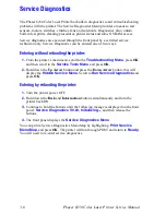
2.
Conventions used in this manual to represent connectors
3.
When instructed to take voltage, continuity or resistance readings on wiring
harness, proceed as follows; Check P/J 232–1 to P/J 210–5 by placing the red
probe (+) of your meter on pin 1 of P/J 232, and place the black probe (–) of your
meter on pin 5 of P/J 210.
4.
When you are instructed to take resistance readings between “P/J 232 <=> P/J
210” (without specified pin numbers), check all pins. Refer to the the section
"Wiring Diagrams" on page 10-1 for the location of all wiring harnesses and pins.
5.
When you are instructed to take a voltage reading, the black probe (–) is
generally connected to a pin that is either RTN (Return) or SG (Signal Ground).
You can substitute any RTN pin or test point in the printer, and you can use FG
(frame ground) in place of any SG pin or test point.
Plug
Jack
6250-503
Summary of Contents for PHASER 6250
Page 1: ...Service Manual Phaser 6250 701P46430 Color Laser Printer ...
Page 2: ......
Page 40: ...1 16 Phaser 6250 Color Laser Printer Service Manual ...
Page 168: ...3 86 Phaser 6250 Color Laser Printer Service Manual ...
Page 214: ...5 26 Phaser 6250 Color Laser Printer Service Manual ...
Page 226: ...7 4 Phaser 6250 Color Laser Printer Service Manual ...
Page 349: ...Service Parts Disassembly 8 123 8 Repeat Steps 1 7 to remove the lower guide 6250 278 ...
Page 376: ...9 4 Phaser 6250 Color Laser Printer Service Manual Print Engine Parts PL 1 1 Covers 6250 286 ...
Page 380: ...9 8 Phaser 6250 Color Laser Printer Service Manual PL 3 1 Paper Feed I 6250 288 ...
Page 382: ...9 10 Phaser 6250 Color Laser Printer Service Manual PL 3 2 Paper Feed II 6250 289 ...
Page 384: ...9 12 Phaser 6250 Color Laser Printer Service Manual PL 3 3 Paper Feed III 6250 290 ...
Page 386: ...9 14 Phaser 6250 Color Laser Printer Service Manual PL 4 1 Housing Assembly Retard 6250 291 ...
Page 388: ...9 16 Phaser 6250 Color Laser Printer Service Manual PL 5 1 Chute Assembly In 6250 292 ...
Page 390: ...9 18 Phaser 6250 Color Laser Printer Service Manual PL 6 1 Chute Assembly Out 6250 293 ...
Page 393: ...Parts List 9 21 This Page Intentionally Left Blank ...
Page 394: ...9 22 Phaser 6250 Color Laser Printer Service Manual PL 7 1 Chute Assembly Exit 6250 294 ...
Page 398: ...9 26 Phaser 6250 Color Laser Printer Service Manual PL 9 1 Xerographics 6250 296 ...
Page 404: ...9 32 Phaser 6250 Color Laser Printer Service Manual PL 12 1 Electrical S6200 240 ...
Page 406: ...9 34 Phaser 6250 Color Laser Printer Service Manual PL 13 1 Harness Assemblies 6250 299 ...
Page 428: ...9 56 Phaser 6250 Color Laser Printer Service Manual ...
Page 435: ...10 7 Map 2 6250 307 ...
Page 436: ...10 8 Phaser 6250 Color Laser Printer Service Manual Map 3 6250 308 ...
Page 437: ...10 9 Map 4 6250 309 ...
Page 439: ...10 11 Map 5 6250 487 ...
Page 441: ...10 13 Map 6 6250 431 ...
Page 462: ...10 34 Phaser 6250 Color Laser Printer Service Manual ...
Page 463: ...A Appendix Reference Contents Printer Status Codes ...
Page 473: ......
Page 474: ...701P46430 ...


