


3 - 86
Phaser 840/850/860/8200 Color Printer - Service Manual
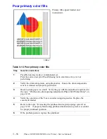
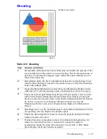
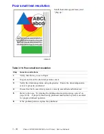
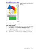
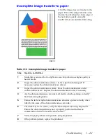
Print transfer jams
1.
If a piece of paper is trapped in the paper preheater, try pushing out the paper by
inserting a stiff piece of cardstock into the paper preheater.
2.
Using diagnostics, test the paper preheater sensors. If the test fails, replace the
paper/drum heater assembly.
3.
Check to see if the upper feed roller drive belt is broken or slipped off of its pulleys. In
such a case, the upper feed roller does not rotate when the lower feed roller rotates.
4.
Check that the feed rollers rotate smoothly and that the front cover is fully closed and
seated.
5.
Check the paper-eject path for obstructions. Ensure no small pieces of paper are
trapped around the stripper fingers or rapid release guide.
6.
Ensure that the transfix roller rotates during the transfix process. See SF168 and
SB467.
7.
Test the sensors in the paper path. Look for damaged or non-operating sensor flags.
8.
Check the transfix solenoid and its cam. Ensure they operate correctly and are properly
lubricated. If lubrication is needed, apply a dab of grease to the contact point between
the cam and the latch and the cam and the cam-advanced spring. Refer to
"Lubrication" on page 6-177.
9.
A stripper finger, or rapid release guide, jam can occur because of broken teeth on the
small section of the back-side of the compound gear. The root cause of this may be also
be due to a lack of transfix cam grease. If you find broken teeth on the compound gear,
check for proper lubrication of the transfix cam. Be careful to ensure that no grease
touches the Y-axis belts. If the belts get contaminated with grease they must be
replaced. wipe off any excess grease to prevent it from dripping onto the belts.
Checking the process motor and drive train
1.
Determine if the process motor runs. If it does not rotate, go to Step 2. If it does rotate,
go to Step 5.
2.
Measure to determine if +40 VDC is being supplied to the motor. If power is applied,
go to Step 3. If it is not, inspect the process motor's wiring harness. If the harness is
functional, then troubleshoot the power control board and power supply. Refer back to
the topic, "Measuring power supply voltages" on page 3-81.
3.
Disconnect the motor's wiring harness. Measure the resistance of the motor's
windings. The expected resistances are listed in Table 3-5 “Motor and solenoid
resistances,” on page 3-84. If the windings are opened, shorted or far out of tolerance,
replace the motor.
4.
If the motor’s winding resistances are within specification, inspect the wiring harness
for nicks, crimps, opens or other problems. If the harness is functional, then replace
the power control board.
5.
Inspect the gear train on the left side of the printer frame; look for stripped gears, loose
or damaged belts, unseated bushings, or broken teeth. Be sure to inspect the inner teeth
on the process-motor gear.
Summary of Contents for Phaser 840
Page 2: ......
Page 12: ...vi Phaser 840 850 860 8200 Color Printer Service Manual ...
Page 52: ...1 36 Phaser 840 850 860 8200 Color Printer Service Manual ...
Page 88: ...2 72 Phaser 840 850 860 8200 Color Printer Service Manual Blank Page ...
Page 134: ...3 118 Phaser 840 850 860 8200 Color Printer Service Manual ...
Page 174: ...4 158 Phaser 840 850 860 8200 Color Printer Service Manual ...
Page 188: ......
Page 250: ...8 234 Phaser 840 850 860 8200 Color Printer Service Manual ...
Page 286: ...270 Phaser 840 850 860 8200 Color Printer Service Manual ...
Page 287: ...071 0723 00 ...


