background image

Troubleshooting

3 - 107

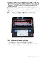
3. Visually check printhead faceplate.

  Closely examine the printhead's faceplate 

to help evaluate whether the cap/wipe/purge assembly’s wiper blade and gasket are 
damaged.  

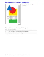
If you see spattered ink on the edges of the printhead, the cap/wipe/purge 

assembly’s gasket may be leaking during the purge cycle.  A misaligned 
printhead or a defective gasket may cause this.  To verify the printhead 

alignment, move the cap/wipe/purge assembly to its purge position and tilt the 
printhead forward until the upper edge of the gasket touches the faceplate.  If 

the left and right sides touch at the same time, the printhead side-to-side 
alignment is correct and the problem is probably due to the gasket.  If not, you 

need to readjust the printhead-to-drum gap.  

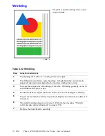
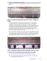
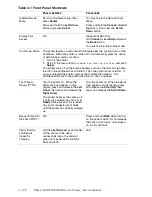
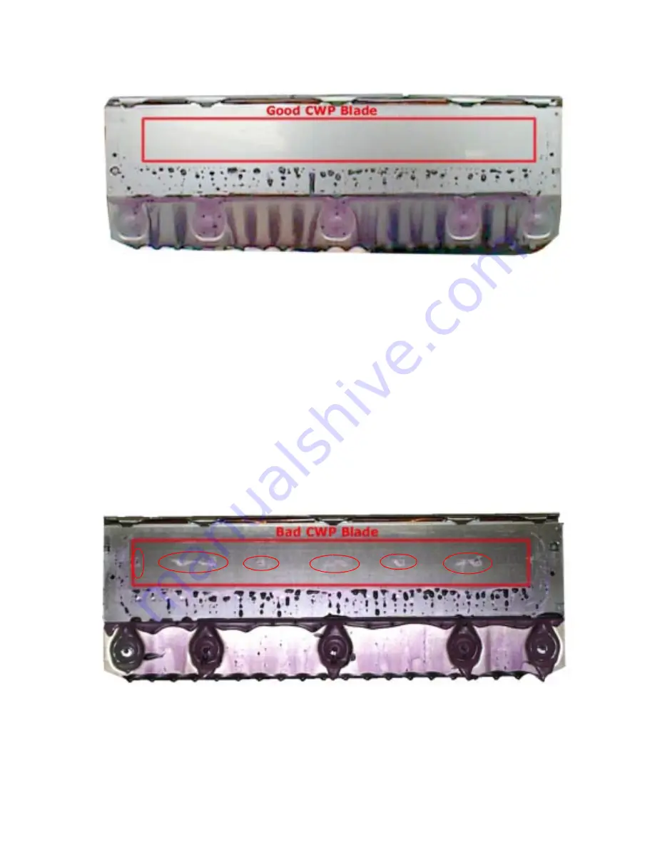
If you see streaks or smudges of wax in the jet area of the printhead's faceplate 

after a purge cycle, the cap/wipe/purge assembly wiper blade is damaged and 
the cap/wipe/purge assembly needs to be replaced.  In this example, the blade 

has several defects; in most cases there is only one smudge or streak.  

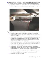
4. Visually check cap/wipe/purge assembly wiper and gasket.


a.

Open the front cover and remove the drum maintenance drawer.  

b.

If not in its standby position, lower the cap/wipe/purge assembly to its 

standby position under the drum.  

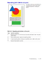
Fig 3-2  Faceplate showing blade wipe with no drops, smudges or 
streaks

Fig 3-3  Faceplate showing streaks and smudges from a poor wipe

Summary of Contents for Phaser 840

Page 1: ...Service Manual With Phaser 8200 Color Printer Addendum P h a s e r C o l o r P r i n t e r 840 850 860 Download Free Service Manual at http printer1 blogspot com ...

Page 2: ......

Page 3: ...her than that contained in the operating instructions unless you are qualified to do so This printing April 2002 071 0723 00 P H A S E R 8 4 0 8 5 0 8 6 0 N E T W O R K C O L O R P R I N T E R S e r v i c e M a n u a l w i t h t h e P h a s e r 8 2 0 0 C o l o r P r i n t e r A d d e n d u m Download Free Service Manual at http printer1 blogspot com ...

Page 4: ...alTalk Macintosh Mac OS and AppleTalk are registered trademarks of Apple Computer Incorporated PCL and HP GL are registered trademarks of Hewlett Packard Corporation MS DOS and Windows are registered trademarks of Microsoft Corporation Novell and NetWare are registered trademarks of Novell Incorporated Sun and Sun Microsystems are registered trademarks of Sun Microsystems Incorporated SPARC is a r...

Page 5: ...de energize the printer You must remove the power cord to disconnect the printer from the mains Keep the power cord accessible for removal in case of an emergency Safety instructions Read all installation instructions carefully before you plug the product into a power source Terms on product CAUTION A personal injury hazard exists that may not be apparent For example a panel may cover the hazardou...

Page 6: ...present Use care when servicing with power on Dangerous voltages may exist at several points in this product To avoid personal injury do not touch exposed connections and components while power is on Disconnect power before removing the power supply shield soldering or replacing components Do not wear jewelry Remove jewelry prior to servicing Rings necklaces and other metallic objects could come i...

Page 7: ...1 12 Circuit Boards 1 13 The printer s I2 C bus 1 15 Printhead Maintenance System 1 16 Sensor Maps 1 17 Combination sensors and their meanings 1 20 Media tray type sensing 1 20 The Main Board 1 21 Front Panel Phaser 840 850 Printers 1 23 Front Panel Phaser 860 1 24 Rear Panel Connections 1 25 Rear Panel Status LEDs 1 28 DIP Switches 1 28 Phaser 840 850 and 860 Printer Differences 1 29 Specificatio...

Page 8: ... ink or light colored ink band running length of print 3 89 Color is uneven 3 90 Streaks or lines down the print 3 91 Scratches parallel to the long axis of printing particularly with film 3 92 Printing too light or too dark 3 93 White portion of print is colored 3 94 Fuzzy Text 3 95 Poor primary color fills 3 96 Ghosting 3 97 Poor small text resolution 3 98 Vertical line appear wavy 3 99 Oil stre...

Page 9: ...thead to drum spacing adjustment Phaser 840 Printer Only 4 146 X axis scale adjustment 4 149 Cap wipe purge assembly belt adjustments 4 150 Drum position encoder gap 4 152 Transfix roller pressure spring adjustment 4 154 Vacuum check Phaser 840 850 Only 4 155 Resetting NVRAM 4 156 Test Prints 5 159 1 X axis motion 5 160 2 Weak missing jet 5 161 3 Color Bands RGBK Dither 5 161 4 Reverse Text 5 162 ...

Page 10: ...r drum heater 7 187 Drum transfix assembly 7 188 Drum position sensor assembly Phaser 840 printer 7 192 Drum position sensor assembly Phaser 850 860 7 194 Printhead 7 196 X axis motor and drive assembly 7 199 Y axis belt drive assembly Phaser 840 printer 7 200 Y axis belt drive assembly Phaser 850 860 printer 7 201 Cap wipe purge assembly Phaser 840 printer 7 202 Cap wipe purge assembly Phaser 850...

Page 11: ...A 241 Inks PA 242 Memory PA 242 Appendix A 243 On site Printhead Troubleshooting Checklist Phaser 340 350 360 380 840 850 A 244 On site Electronics Troubleshooting Checklist Phaser 840 850 A 250 Z840 z850 Electronics Troubleshooting Guide A 253 On site Printhead Troubleshooting Checklist Phaser 860 8200 A 261 On site Electronics Troubleshooting Checklist Phaser 860 A 266 ...

Page 12: ...vi Phaser 840 850 860 8200 Color Printer Service Manual ...

Page 13: ...ms 2 59 22 000 Fault Codes and Actions 2 60 Front Panel Fault History Log Error Codes and Messages 2 71 Electrical Interface RAP Table 3 73 Media and Paper Path RAP Table 3 73 Print and Image Quality Problems RAP Table 3 74 Macintosh Printing Problems RAP Table 3 74 Motor and solenoid resistances 3 84 Not Printing 3 88 Missing or light colored ink band 3 89 Color is uneven 3 90 Streaks or lines do...

Page 14: ... 127 Test Print Menu 5 159 Maintenance Kit Life 6 176 Cabinet FRUs 8 209 Imaging FRUs 8 210 Paper path FRUs 8 213 Motor and fan FRUs 8 215 Circuit board FRUs 8 216 Solenoid and clutch FRUs 8 219 Gear and belt FRUs 8 221 Sensor and flag FRUs 8 223 High capacity Paper Tray FRUs 8 225 Service tools 8 226 Supplies and accessories 8 227 ...

Page 15: ...850 printer rear panel 1 26 Phaser 860 printer rear panel 1 27 Attaching the service load connector to J250 3 83 Faceplate showing blade wipe with no drops smudges or streaks 3 107 Faceplate showing streaks and smudges from a poor wipe 3 107 Connecting the vacuum gauge to the printer 3 108 Maintenance tray showing good purge 3 111 Damaged printhead data cable 3 113 Inadvertently disconnected therm...

Page 16: ... alignment 7 194 Removing the drum position sensor assembly Phaser 850 printer 7 195 Plugging the reservoir holes 7 196 Removing the printhead 7 197 Removing the x axis motor and drive assembly 7 199 Removing the Y axis belt drive assembly Phaser 840 printer 7 200 Removing the Y axis belt drive assembly Phaser 850 860 printer 7 201 Removing the cap wipe purge assembly Phaser 840 printer 7 203 Remo...

Page 17: ...operation detailed removal replacement procedures configuration page details and verifying printer operation are located on the companion Color Printer Service Support Resources CD ROM To ensure complete understanding of the product we recommend participation in Phaser 840 850 860 printer service training Fig 1 1 The Phaser 840 850 printer shown with optional High Capacity Paper Tray Assembly Fig ...

Page 18: ... can print one image and process the data for the next image at the same time First Page Preview mode prints the first page of a multiple page print job while holding the remainder of the job pending front panel approval The Phaser 840DX The extended features option has all the features of the Phaser 840 Plus printer but includes additional RAM to bring the printer to 128 Mbytes of RAM It also inc...

Page 19: ...otocol support for EtherTalk Novell NetWare NDS TCP IP and DHCP When installed this card disables the standard 10baseT port A third card provides a Token Ring board providing protocol support for TokenTalk Novell NetWare NDS and TCP IP When inserted this card also disables the standard 10baseT port A second rear panel slot accommodates an internal IDE hard drive for print job collation job account...

Page 20: ...site service The Phaser 850DX The extended features DX option has all the features of the Phaser 850DP printer but includes additional RAM to bring the printer to 128 Mbytes of RAM It also includes a High Capacity Paper Tray and an internal IDE hard drive Like the Phaser 840 printer all printers support four available paper trays They also support the optional 500 sheet High Capacity Paper Tray As...

Page 21: ...y and 3 years of on site service The Phaser 860DX The extended features DX option has all the features of the Phaser 860DP printer but includes a High capacity Paper Tray and an internal IDE hard drive All printers support five available paper trays Two A and A4 trays are meant for paper and low volumes of transparencies two other A and A4 trays are meant for label stock and high volume transparen...

Page 22: ...printing is delayed until the password is entered on the printer s control panel Using the same password will cause any previous jobs s to be deleted A secure job that has not been printed or released is retained on disk through power cycles This function requires the internal hard drive Saved Print Jobs Saved print allows the user to save print jobs to the internal hard drive of the printer The p...

Page 23: ... Presence Detect ROM Unbuffered Latency of 2 9 address columns Phaser 850 printer allows 32 Mbytes DIMM to be in 8 columns Maximum of 2 8 cm 1 1 in in height Phaser 840 printer only SDRAM DIMMs from other Phaser printers such as the Phaser 740 and Phaser 780 color printers may be too tall to fit inside a Phaser 840 printer Upon power up the image processor interrogates the 256 byte Serial Presence...

Page 24: ...stalled RAM and printer capabilities Feature 32 Mbytes 840N 850N 64 Mbytes 840DP 850DP 128 Mbytes 840DX 850DX Fast Color draft printing yes yes yes Standard Printing yes yes yes Enhanced Printing yes yes yes High Resolution Photo Printing no yes yes 2 sided printing no yes The printer supports fast standard and enhanced 2 sided prints yes The printer supports 2 sided high resolution 1200 x 600 dpi...

Page 25: ... enabled Table 1 2 Acceptible SDRAM DIMMs Size Maker Part Number Printer 32 Mbytes Samsung KMM366S403CTL G0 840 850 32 Mbytes Micron MT16LSDT464AG 662XX 840 850 64 Mbytes Samsung KMM366S823BTL G0 840 850 64 Mbytes Micron Crucial CT8M64S4D10 MBTBGLP 840 850 32 Mbyte Samsung KMM366S424DTS GL 850 see note 64 Mbyte Samsung KMM366S823DTS GL 850 64 Mbyte Samsung KMM366S924BTS GL 850 128 Mbytes Samsung K...

Page 26: ...eat detail such as data width clock delay number of address columns and row refresh rate and more If the SODIMM does not meet the required specifications it will be not be used If there are no good SODIMMs you will receive a RAM error If one SODIMM is good you will receive a temporary error message and the printer will continue with power up Print the Configuration Page and check the item Installe...

Page 27: ... capabilities Feature 64 Mbytes 860B 860N 128 Mbytes 860DP 860DPF 860DX Fast Color draft printing yes yes Standard Printing yes yes Enhanced Printing yes yes High Resolution Photo Printing no yes 2 sided printing no yes The printer supports 2 sided high resolution 1200 x 600 dpi print Color PCL 5c yes yes Pipelining no yes Collation requires hard drive no yes Job accounting 500 records 500 records...

Page 28: ...Manual Print Engine Assemblies 840 850 860 Fig 1 3 Internal features of the print engine 0388 0 Ink load assembly X axis drive and motor Paper feed motor Paper drum heater Cap wipe purge assembly Transfix roller Process motor Y axis motor Drum Printhead ...

Page 29: ...and many of the printer motors The power supply converts the AC line voltage into internal AC and DC voltages The front panel provides a user interface to the printer The printhead drive board a part of the printhead manages the signals and voltages of the printhead s printing elements and sensors The optional network card Phaser 840 and 850 only and internal hard drive could be considered eight a...

Page 30: ...ards of the print engine right rear view Phaser 860 0388 04 I O board left Power control board Printhead drive board Internal hard drive Network card Main board Power supply Drum Maintenance counter EEPROM P860 004 Power Supply Main Board Internal Hard Drive I O Board left Power Control Board Printhead Drive Board Drum Maintenance Counter EEPROM ...

Page 31: ...n poll the I O boards for the state of the printer s sensors as well as actuate the printer s solenoids This data bus greatly simplifies the wiring that would otherwise be required for monitoring numerous sensors and solenoids The I2 C bus also extends down to the High Capacity Paper Trays Fig 1 7 The printer s I2 C bus 0388 05 I2 C bus High capacity Paper Tray connection ...

Page 32: ...tem used to clean the printhead faceplate and clear clogs from the printhead nozzles The system consists of a vacuum pump assembly the cap wipe purge assembly and the cap wipe purge carriage drive Fig 1 8 Printhead maintenance system of the print engine Cap wipe purge carriage drive Cap wipe purge assembly Vacuum pump assembly 0388 06 ...

Page 33: ...drum Note Unlike the Phaser 840 printer the Phaser 850 860 printer does not have a separate drum home position sensor Fig 1 9 Sensors and switches on the right side of the print engine 0388 07 Maintenance blade position sensor Paper empty sensor Cap wipe purge home sensor A4 size media sensor Ink load cover sensor Ink stick low sensor Ink stick out sensor Exit tray full sensor Top cover switch Fro...

Page 34: ... of the print engine Drum encoder sensor Process gear position sensor Drum home position sensor Phaser 840 only Drum temperature sensor Preheater exit sensor Duplex paper sensor Transfix exit sensor 0388 34 Preheater exit sensor located on inside wall of drum transfix frame Drum Transfix roller Preheater ...

Page 35: ...ies to position the assemblies For example the printhead could be tilted forward and crash into the raised cap wipe purge assembly Before turning on the printer ensure the printhead is tilted forward centered in front of the drum and the cap wipe purge assembly is in the retracted home position The tilt cam gear should be disengaged from the gear drive train Electric clutches and solenoids are use...

Page 36: ... paper as well as low volumes of A size transparency film Metric Letter A4 size This tray is used for 210 x 297 mm Metric paper as well as low volumes of A4 size transparency film High volume Transparency Label A This tray supports high volumes of U S size transparency film as well as laser quality adhesive label stock High volume Transparency Label A4 This tray supports high volumes of Metric siz...

Page 37: ...a 10 100BaseT port for the Phaser 850 860 printer not enabled in the Phaser 860B For the Phaser 840 printer a plug in SCSI interface adapter board provides a SCSI port for an external hard drive or scanner The Phaser 840 printer stores unique printer status and PostScript values in its socketed NVRAM and EEPROM modules The printer s Ethernet address unique to each printer is stored in the EEPROM p...

Page 38: ...e Manual Fig 1 13 Features of the Phaser 850 printer main board Fig 1 14 Features of the Phaser 860 Main Board 0388 76 RAM DIMMs EEPROM Printer ID Code ROM module P860 002 Hard Drive RAM SODIMMs EEPROM Printer ID ROM Upgrade Code DIMM Factory Code ROM ...

Page 39: ...ine status includes messages such as Out of paper Paper Jam Add ink as well as error messages Customers can review and modify certain NVRAM I O ports and peripheral parameters Buttons Four of the six buttons are arranged as a diamond shaped keypad The other two buttons are used as Select and Help Refer to Check Value Menu Parameters on page 4 135 for details on using the front panel controls to en...

Page 40: ...s includes messages such as Out of paper Paper Jam Add ink and error messages Customers can review and modify certain NVRAM I O ports and peripheral parameters Buttons 1 Status Indicator light 2 LCD Display Screen 3 Cancel 4 Back or Exit 5 Scroll Up and Scroll Down 6 OK 7 i will display additional or help infromation regarding the message or menu item currently displayed on the screen Refer to Fro...

Page 41: ...slots With the addition of a PhaserShare network card in one slot the printer can feature either of these connector combinations LocalTalk connector ThinNet 10Base2 and Twisted Pair 100BaseT Ethernet or Token Ring connectors Note When an Ethernet or Token Ring PhaserShare card is installed the printer s built in 10BaseT Ethernet port is disabled The second slot accommodates an internal IDE hard dr...

Page 42: ...l 5 pin connector accommodates a service RS 232 cable from a PC or Macintosh computer running PC based diagnostics The rear panel also includes two option slots One slot accommodates a Token Ring Card When the Token Ring card is installed the printer s built in 10 100BaseT Ethernet port is disabled The second slot accommodates an internal IDE hard drive for print job collation job accounting and f...

Page 43: ...284C For the Phaser 860 printer it can also be used to connect a parallel interface scanner Twisted Pair 10 100BaseT Ethernet connector A Universal Serial Bus USB port An optional hard drive can be installed on the main board Optional Network cards are not supported for the Phaser 860 Fig 1 19 Phaser 860 printer rear panel P860 005 USB RESET PS PE 4 1 2 3 Ethernet TP RCV XMT Parallel Service Only ...

Page 44: ...7 5 If the LEDs are blinking in a repeating pattern other than normal operating health status as described refer to the topic Error Codes and Messages on page 2 37 DIP Switches Four DIP switches allow you to reset the printer or place the printer in different operating modes You must set the switches before power is turned on to enter the selected mode Table 1 6 Rear panel DIP switch settings Func...

Page 45: ...ht of the RAM DIMMs the main board will accept since it uses angled RAM DIMM connectors PC66 compliant Uses the smaller 144 pin SODIMMs PC100 compliant Power control board Improved fusing Resettable fuses by disconnecting AC power on 5v and 40v High Capacity Paper Tray leads No x axis fuse 40V service load connector no longer needed Printhead The Phaser 850 printhead mount has been factory calibra...

Page 46: ... dramatically improve reliability Round pick roller to improve reliablility The pick roller now uses the same clutch as the upper feed roller and the cap wip purge drive New Drum Maintenace Cam to support new Drum Maintenance alogrithms Preheater A new paper preheater designed to accommodate the travel of the paper preheater entry flags is used in the Phaser 850 printer The preheater is reverse co...

Page 47: ... Approximately 36 kgs 79 lbs Print engine weight only add 9 kgs 20 lbs for each optional High Capacity Paper Tray Assembly Table 1 9 Printer installation clearances Clearances Value Top 45 7 cm 18 ins Left 10 2 cm 4 ins Right 10 2 cm 4 ins Front Unrestricted to replace trays and clear paper jams Rear 10 2 cm 4 ins Bottom No obstruction under printer that could block its cooling vents Mounting surf...

Page 48: ...int times do not include image processing time which varies due to image complexity 25 mm 1 in margins assumed with 35 ink coverage Minimum printing margins All sides 5 mm 0 2 in Legal size 1 inch Top and Bottom 5mm right and left sides Envelope margins vary see user guide for specifications Maximum print area A size 8 1 x 10 6 in A4 size 200 x 283 mm Legal size 8 1 x 12 in Phaser 860 only Usable ...

Page 49: ...eristic Specification Primary line voltages 87 to 132 VAC 115 VAC nominal 174 to 264 VAC 220 VAC nominal Input voltage range is auto sensed Primary voltage frequency range 47 to 63 Hz Power consumption 200 watts standby 300 watts at idle 600 watts during printing Maximum power consumption 1000 watts during warm up Current rating 115 VAC configuration 8 amp max 1 amp min 220 VAC configuration 4 amp...

Page 50: ...e 89 392 EEC Machinery Directive Table 1 12 Environmental specifications Characteristic Specification Temperature Operating Storage and shipping 10 to 32 C 50 to 90 F 30 to 60 C 22 to 140 F Humidity Operating Non operating 10 to 80 relative humidity non condensing 10 to 95 relative humidity non condensing Altitude Operating Non operating 0 to 2400 m 8 000 ft at 25 C 0 to 15000 m 50 000 ft Vibratio...

Page 51: ... B VCCI CISPR 22 Class B EN61000 3 2 Flicker on AC Mains Susceptibility The packaged product meets National Safe Transit Committee Test Procedures Listed UL 1950 Information Technology Equipment Certified to CSA C22 2 No 950 Safety of Information Technology Equipment Including Electrical Business Equipment GS licensed IEC 950 1991 Second Edition EN60950 Information Technology Equipment ...

Page 52: ...1 36 Phaser 840 850 860 8200 Color Printer Service Manual ...

Page 53: ...s are listed in the following table Other failures are indicated by the failure being printed on the Startup Page After successful power up the left LED flashes at a regular heartbeat rate The front panel Power light turns on the Error light flashes and the LCD is cleared When troubleshooting Rear Panel LED Codes try reseating the affected components first If the problem continues then replace the...

Page 54: ...e of the Ethernet chip on the main board 18 TEA error Phaser 850 only The error occurs during power up self tests when one of the main devices previously enabled fails to respond unexpectedly causing a TEA Normal TEAs cause the corresponding specific error This could be caused by either the Code ROM or Main Board none SCSI Phaser 840 only This test verifies the functionality of the SCSI I O proces...

Page 55: ...ernal loopback failure none Token Ring Option Card Phaser 840 850 Only Token Ring is not supported in the Phaser 860 printer This test verifies the functionality of the processor chip Any test failures with this component are treated as non fatal errors with the error information written to the Start Page If a failure is detected the message Token Ring Option Card with one of the following message...

Page 56: ...er to print a Startup Page with the error message on it BIST and POST errors are not stored in the fault history logs The BIST Built In Self Test These tests occur immediately at power up before the front panel is initialized Table 2 2 BIST Rear Panel LED Codes PS LED PE LED Description 1 Blink and then off 1 Blink andthen off The power supply could not remain regulated when the DC power was appli...

Page 57: ...ed Verify the IIC cable connections then replace the I O Right NO FRONT PANEL MESSAGE WILL BE DISPLAYED FOR THIS ERROR 5 5 01 The front panel is not detected Verify the IIC cable connections and the state of the front panel sensor Replace the front panel NO FRONT PANEL MESSAGE WILL BE DISPLAYED FOR THIS ERROR 6 6 01 The duplex sensor is detected but the front panel is not responding Verify the IIC...

Page 58: ...d then the power control board Soft Error 18 xx Optional Token Ring card failures This failure should never occur the Phaser 860 does not support optional cards If this error occurs check the main board to power control board connector for damage Replace the main board and then the power control board 20 20 01 I O Left not detected Verify the IIC cable connetion Replace the I O Left 20 20 02 I O L...

Page 59: ...r is out of range Replace the printhead Soft Error 22 01 Maintenance Kit counter is not responding Check for bent pins on the counter Reseat then replace the maintenance kit Soft Error 22 02 Intermittent response from the maintenance kit counter Reseat the maintenance kit cycle power then replace the maintenance kit Table 2 3 POST Power On Self Test Error Messages cont d PS PE and Front Panel LEDs...

Page 60: ...ause the printer to automatically reboot and no message is displayed on the Front Panel The fault codes are saved into non volatile memory and can be retrieved from the fault history CPU exceptions are indicated by a 7 in the tenths place of the fault code xx yyy 7x The error code indicates both the PowerPC exception number and the region of firmware that was executing when the exception occurred ...

Page 61: ...t early initialization code the engine firmware was unable to start the service diagnostics task 4 000 PC PROCESS CONTROL SUPERVISOR 04 001 40 PC_DEV_FAULT_HEAD_ READ Failure reading printhead NVRAM data check the wiring to the printhead I2 C bus and other hardware May also be related to ESD 04 002 41 PC_DEV_FAULT_HEAD_Z EROS Printhead NVRAM data was all 0s has this printhead been through normaliz...

Page 62: ...was then displaced to the right 3 8 mm 0 15 in and the disengage was repeated but the motor stalled again This fault is then declared Table 2 4 Front Panel Fault History Log Error Codes and Messages Error code Definition Remove obstruction printhead heater cable C W P assembly poorly installed ink loader 4 013 43 Printhead unable to tilt Tilt arm motion obstructed Tilt arm parked on its locking pi...

Page 63: ...e printer determined at power up that the printhead was warm enough not to need cleaning and while the printer was warming up the printhead temperature dropped below the head clean needed threshold Something may be wrong with a heater 4 019 40 PC_DEV_FAULT_ 193DPI_CAL Calibration Failure Target Volt Sec Area of Fast Color mode could not be achieved Check the printhead cabling Replace the printhead...

Page 64: ...x33 Bad Command Result during Drum warm up processing of a PostScript command message in pc_process_message returned SERVICE_NEEDED during the drum warm up period This should never happen and is flagged by pc_warmup_seq as an error 4 059 66 PC_PROG_FAULT 0x3b Bad Command Result during Big Drop Flush Processing of a PostScript command message in pc_process_message returned SERVICE_NEEDED during the...

Page 65: ...ndication that the motor coil s is open or shorted or the X axis motor fuse has opened Follow the procedure Testing motor and solenoid resistances on page 84 of this manual Try diagnostics to verify X axis movement If there is not any movement it is propable that the fuse is defective The fuse is located in the power control board the whole baord should be replaced Some Phaser 840 printers in the ...

Page 66: ... HAS SOLIDIFIED PRIOR TO THE REMOVAL OF THE PRINTER FROM THE LTA Remove the printer and inspect the LTA connection If there is any damage to the connector replace the lower tray assembly or connector If there is not any damage remove and inspect the connnection to the printer This connection is on the left side of the printer next to the left rear foot it is mounted with two e rings and plugs into...

Page 67: ...ave occurred Run diagnostics to verify clutch and sensor operation Also verify that the shaft is properly assembled Table 2 4 Front Panel Fault History Log Error Codes and Messages Error code Definition 7 004 46 Maintenance blade position sensor right I O board failed to detect transitions of the drum maintenance home flag Observe drum maintenance home flag motion while turning on the printer Does...

Page 68: ...ed message in pm_sleep_for An unexpected ITC message was received by pm_get_message during processing of pm_sleep_for 7 052 62 PM_PROG_FAULT_ FUNCS 20 Bad message ID in pm_update_dmc_status The ITC message received and passed to pm_update_dmc status did not match any DMC status message that the Process Motor task was expecting Table 2 4 Front Panel Fault History Log Error Codes and Messages Error ...

Page 69: ... and Messages Error code Definition 8 001 44 C W P can t find home Check alignment of C W P assembly belts C W P belts aligned OK With C W P out of home position observe exit roller while turning on the printer Does the exit roller turn No Replace C W P clutch or reseat belt No Replace or reseat flag Replace power control board With C W P out of home position observe C W P assembly motion while tu...

Page 70: ...LT_M_ TWANGER Malfunction of the ink level sensor in the magenta reservoir Replace the printhead 9 003 47 IL_FAULT_Y_ TWANGER Malfunction of the ink level sensor in the yellow reservoir Replace the printhead 9 004 48 IL_FAULT_K_ TWANGER Malfunction of the ink level sensor in the black reservoir Replace the printhead 9 005 40 IL_FAULT_C_JAM The cyan ink melt heater is on but ink does not seem to be...

Page 71: ...he DMC library was attempting to locate an event parameter block in its linked list The block was not found 11 020 61 DMC event parameter block not found The DMC library was attempting to locate a timer parameter block in its linked list The block was not found 11 022 63 DMC_PROG_FAULT 22 Invalid Get Device State Argument The ITC message base passed into dmc_get_device_stat was not a valid DMC typ...

Page 72: ...rinthead via the I2C interface failed This can happen if the wires are loose to the printhead or if the NVRAM part does not ACK the read request 12 000 INTER TASK COMMUNICATION PROGRAM FAULT CODES 12 002 62 ITC_PROG_FAULT 2 This is a secondary failure Something failed resulting in the message stack overflowing Unable to Send Message The ITC send message function itc_send_msg was unable to place th...

Page 73: ...place the printhead 13 036 48 TCH_RESERVOIR_SLOW The reservoir heater is not heating at all or is not heating as quickly as it should Check the printhead cabling Replace the printhead 13 037 61 TCH_RESERVOIR_ADC_ IS_BAD The analog to digital converter appears to be bad Try reseating the printhead data cable Then reseat the main board If the problem continues try replacing the main board and then t...

Page 74: ...heck for an open connection Replace the paper preheater Replace the power supply 16 005 47 TCP_THERMISTOR_ADC _BAD An inalid reading is being reported by the preheater thermistor Verify the connections to the paper preheater replace the paper preheater replace the main board and then replace the power control board 19 000 PRINTHEAD CALIBRATION PROGRAM FAULT CODES 19 001 4X HC_DEV_FAULT 0x01 Occurs...

Page 75: ...ensor 16 VE_DM CYCLE_DONE out of order 17 VE_TF_ROLLER_LIFTED out of order 18 Duplex length measured to be too long 19 Timing delay affected transfix staging 20 Media not visible in top cover not used 21 High Capacity media length too long not used 22 Unknown reason T indicates whether a timeout or an event occurred 0 event An unexpected event occurred 1 timeout Time expired without the expected e...

Page 76: ...r tray is clamping the media in the tray usually there will be black marks on the media a Media loaded poorly b Problem with bias block c Bad batch of media too wide a Remove bad sheets and reload tray more carefully b Flip media over or replace media c Use long grain media d Use heavier weight media Media is found above the pick arm a A sheet of paper from the bottom of the stack is lining the ra...

Page 77: ...front panel sensors or replace front panel e Replace power supply f Use anti static spray for office equipment 22 201 08 Unexpected Lower tray present sensor event in Lower Feeder 2 with media in Lower Feeder 1 Same as 22 101 06 22 203 00 Unexpected Lower tray present sensor event in Lower Feeder 1 with media in Lower Feeder 1 Same as 22 101 06 22 204 00 Sticky pick flag in Lower Feeder 1 with med...

Page 78: ...ia inspect and reload 6 Media is folded damaged or deformed a Media cannot get out of the tray a Use diagnostics to verify pick roller motion and clutch activation 7 Media found flat in tray chronic problem a Problem with pick clutch b Too much pick shaft motion a Reinstall or replace the pick clutch b Check bushings and e clips 8 Media damage in center a Pick pad a Don t load media too close to f...

Page 79: ...05 in the fault history a Standard tray pick roller clutch slipping a Replace the pick roller clutch see Service Bulletin 462 22 508 08 Unexpected preheat entry sensor left side event Can be caused by media off the sensor too soon a Verify that the lower tray is properly loaded 1 Skew a Last sheet in tray b First sheet in tray c Failure of deskew system a Refill tray s b Make sure tray s is loaded...

Page 80: ...ed in tray a Media gets out of the tray but hits the sensors at the wrong times a Remove media inspect and reload 22 512 14 Time out on preheat exit sensor 1 Damage on the right corner of A Size media a Probable preheater problem a Replace preheater 2 Tight wrinkles across media a Short grained media b Too much drag in preheater a Use long grained or heavier weight media b Replace preheater 3 Medi...

Page 81: ...n lighter media 32 22 541 05 Unexpected A A4 sensor event Same as 22 511 02 22 542 17 Time out on preheat exit sensor duplex Unexpected duplex sensor event Same as 22 512 14 22 548 03 Duplex long declaration determined from duplex sensor 1 More than one sheet in duplex path a Media was pulled from exit into duplex while printing b Multiple pick a Empty exit bin b Retry 22 600 01 Command stop event...

Page 82: ...n 2 Skew a Last sheet in tray b First sheet in tray c Failure of deskew system a Refill tray s b Make sure tray s is loaded properly and media is square in tray c Check deskew fingers If chronic check preheat entry assembly for deformation 3 Media perfectly straight a Media path motor stall a Use diagnostics to run verify drive current requirements or feel for unevenness in motor rotation by manua...

Page 83: ... Replace front cover display assembly 7 Media goes back down simplex path a Roller slip b Media impeded from exiting by top cover c Media impeded from exiting by a tall stack of paper a Replace exit roller insure exit idler rollers are providing adequate force b Reassemble top cover c Remove media from output tray 22 700 02 Command stop event while transfixing Typically becuase of a positioning er...

Page 84: ... not able to exit cleanly a Problem with idler rollers on exit cover b Top cover installed too high c Problem with exit roller a Ensure all idler roller springs are present and not damaged b Reassemble top cover c Ensure that all bushings and e clips are properly installed 5 Printing transparencies a Printer running at fast color speed a Reboot printer and rerun prints 22 706 08 Y axis declared pa...

Page 85: ...n inside of front door If chronic check preheat entry assembly for deformation 2 Media jammed on stripper fingers or rapid release guide folded corner a Missing support foil clear L shaped plastic media guide on the front left side of the lower tray b Folded in tray a Replace Lower tray b Remove media inspect and reload 3 Media jammed on stripper fingers or rapid release guide bad media a Damaged ...

Page 86: ...ivoting blue lower exit guide b Replace sensor assembly 10 Media under transfix roller right at stripper fingers a Eccentric solenoid problem b Transfix cam problem c Cam spring problem a Replace eccentric solenoid b Replace cam c Replace drum transfix assembly 11 Media doesn t make it to the transfix roller a Too much drag in drive train or preheater a Short grained media a Use PC based diagnosti...

Page 87: ...OTOR_STALL Not used as a device fault condition 31 003 4x MP_FAULT_PREHEAT_ EXIT_SENSOR_BAD Declared when the sensors around the preheater exit sensor indicate the presence or absence of media contrary to that indicated by the preheater exit sensor This is usually caused by a piece of media stuck in the preheater exit sensor 31 003 42 Use diagnostics sensor tests to locate the blocked sensor 31 04...

Page 88: ...2 72 Phaser 840 850 860 8200 Color Printer Service Manual Blank Page ...

Page 89: ... Paper Path Problems RAP Table Table 3 1 Electrical Interface RAP Table Problem on Page System Power Up Sequence page 76 Inoperative Printer No Lights No Sound on power up page 80 Verifying Main Board CPU Operation page 80 Verifying Print Engine operation by its startup page page 81 Verifying Power Supply and Measuring Voltages page 81 Inspecting the power supply fuses page 82 Testing for shorted ...

Page 90: ...portion of print is colored or marked page 94 Fuzzy text page 95 Poor primary color fills page 96 Ghosting page 97 Poor small text resolution page 98 Vertical line appears wavy page 99 Oil streaks on print top or bottom page 100 Incomplete image transfer to paper page 101 Ink smears on first side of duplex print page 102 Repeating print defects on print page 103 Wrinkling page 104 Image is offset ...

Page 91: ...Startup Log and press Select The log can also be accessed remotely via PhaserLink 2 0 The logs lists events chronologically The log is limited in length logging stops when the log is full The log is stored in RAM only so new data is stored each time the printer s power is cycled Phaser 860 The Phaser 860 printer maintains four logs in memory detailing network functions The logs contain Netware TCP...

Page 92: ... toggle and the front panel LEDs are turned on The front panel display is blank This test takes from 4 to 15 seconds depending on installed RAM 3 If POST diagnostics pass the front panel Error LED is turned off and the front panel displays the Tektronix logo while the mechanical initialization checks are performed If an error is detected the Phaser 850 printer flashes the front panel Error LED wit...

Page 93: ... After the print engine is in a known valid state the AC heaters are enabled and the front panel display shows the warm up progress The Ready LED flashes when warm up completes the Ready LED lights solid 10 The drum begins to rotate 11 If the temperature of the printhead ink reservoirs or jetstack are below the purge threshold then the printer performs a head clean cycle a When the ink in the prin...

Page 94: ...l displays the Xerox logo If an error is detected the error message is displayed on the LCD and the printer flashes the LEDs with a repeating error code pattern 6 The VxWorks operating system is initialized and engine code is started This takes about 15 seconds The Xerox logo is displayed 7 The mechanical initialization is conditional on the initial position of the printhead and cap wipe purge ass...

Page 95: ...isplay shows the warm up progress The Ready LED flashes when warm up completes the Ready LED lights solid 13 The drum begins to rotate 14 If the temperature of the printhead ink reservoirs or jetstack are below the purge threshold then the printer performs a head clean cycle a When the ink in the printhead is molten and printhead temperatures are correct the cap wipe purge assembly is positioned t...

Page 96: ... and no sound upon power up Phaser 850 A manufacturing process error resulted in some power control board brackets getting bent The serial number range for this potential problem is M0A7600 to M0D3800 These bent brackets prevent the 40v loopback connector from fully seating and in some cases can result in it disconnecting due to shipping vibrations When the power switch is turned on with a disconn...

Page 97: ...lves three steps Checking for proper AC voltage Inspecting the power supply fuses Testing for a shorted motor or solenoid driver which shuts down the power supply See SF 156 Phaser 840 only Measuring power supply voltages Warning AC line voltages are present on the power supply and possibly in the printer via the heaters while the printer is plugged into an AC outlet even if the power switch is of...

Page 98: ...C heaters within the printer they protect the power supply from most often a shorted triac If F2 or F3 blows replace the power supply rather than the fuse Otherwise with the fuse replaced but the triac shorted AC power may be applied to the heater without the printer even being turned on resulting in a thermal runaway condition If the fuses are functional but the printer s power supply does not ou...

Page 99: ...EDs replace the power supply 5 Turn off the printer Reconnect the 40 volt loopback connector to the power control board then disconnect all load connectors from the power control board Turn on the printer If the rear panel LEDs still do not illuminate the power control board has a shorted driver and must be replaced If the LEDs do illuminate isolate which motor or fan is overloading the power cont...

Page 100: ...ter Rotate the motor s drive shaft slightly while taking the measurement Table 3 5 Motor and solenoid resistances Motor or solenoid Phaser 840 printer Resistance approximately Phaser 850 860 Printer Resistance approximately Process motor 2 9 ohms 15 Difficult to measure due to variability at the brush commutator interface 4 3 ohms 15 Difficult to measure due to variability at the brush commutator ...

Page 101: ...il there should be a small gap between the opposite edge of the stack of paper and the opposite side rail The Phaser 860 has tabs on the back stop to prevent over filling the tray 3 In humid environments keep media sealed in packaging until it is needed for printing Flip over the media in the tray 4 When installing paper push down the stack of paper until the tray s lift plate locks to the bottom ...

Page 102: ...back side of the compound gear The root cause of this may be also be due to a lack of transfix cam grease If you find broken teeth on the compound gear check for proper lubrication of the transfix cam Be careful to ensure that no grease touches the Y axis belts If the belts get contaminated with grease they must be replaced wipe off any excess grease to prevent it from dripping onto the belts Chec...

Page 103: ...ller is not visibly dirty so that it picks up a sheet of media smoothly and evenly 4 Check the upper and lower feed rollers Also make sure that the front door is properly closed 5 Check the flexible white paper deskew springs on the inside of the front cover Ensure that none are bent damaged or missing 6 The printer should be installed on a flat level surface 7 Ensure the pick guide assembly is pr...

Page 104: ...able 3 6 Not Printing Step Question and Actions 1 No drive voltages to printhead Check for a loose connector leading to the printhead 2 Replace the Power Contol Board 3 Refer to the topic Evaluating the printhead and cap wipe purge system on page 3 106 A properly functioning printhead maintenance system is essential for proper printhead operation 4 Replace the Printhead ...

Page 105: ...ermine which jet is not performing If not already tried perform up to three printhead cleaning cycles to try to clean a clogged jet If unsuccessful turn off the printer and allow the printhead to cool for 4 hours Perform another cleaning cycle 3 Refer to the topic Evaluating the printhead and cap wipe purge system on page 3 106 A properly functioning printhead maintenance system is essential for p...

Page 106: ... drum maintenance drawer Inspect the operation of the drum maintenance cam roller and the left and right cam actuators it pushes against 2 Refer to the topic Evaluating the printhead and cap wipe purge system on page 3 106 A properly functioning printhead maintenance system is essential for proper printhead operation 3 Perform the procedure Printhead to drum spacing adjustment Phaser 840 Printer O...

Page 107: ...lewing of the printhead Replace the X axis drive if indicated 4 Calibrate the x axis scale as described in the topic X axis scale adjustment on page 4 149 5 Check for media in the exit path 6 If streaks are on the front side of a 2 sided print the paper preheater may be scraping ink off the print Look for ink shaving alongside the streak Clean the preheater using the front panel initiated cleaning...

Page 108: ... the paper pick and early transport of the transparency film Try changing the paper pick guide front door or maintenance drawer 3 A scratch or smear can be caused by debris built up on the paper preheater heating surfaces Run the front panel cleaning procedure Remove Ink smears Force a sheet of thick 65 to 80 lb paper through the paper preheater to buff the paper preheater heating surfaces With th...

Page 109: ... tray installed and that the tray is correctly set for the media loaded in it Printing on paper in transparency mode significantly darkens a print Try a different color correction setting 2 Perform the procedure Printhead to drum spacing adjustment Phaser 840 Printer Only on page 4 146 3 Verify that the printhead setting Head Adjust in the hidden service menu is set to 128 ...

Page 110: ...necessary replace the maintenance kit 2 Clean the rapid release guide 3 The paper preheater may be contaminated with ink Clean for ink smears using the front panel Troubleshooting function Remove Ink Smears 4 Run diagnostics to ensure that printer temperatures are in tolerance Ensure that the drum heater is properly positioned Print using a smoother laser quality paper Some recycled paper brands m...

Page 111: ...inter Only on page 4 146 2 Verify the drum temperature using diagnostics Ensure the drum temperature sensor is clean and properly positioned 3 Refer to the topic Evaluating the printhead and cap wipe purge system on page 3 106 A properly functioning printhead maintenance system is essential for proper printhead operation 4 Verify the operation of the Y axis encoder using diagnostics Replace the en...

Page 112: ...s Ensure the drum temperature sensor is cleaned and properly positioned 3 Head to drum gap is too small Verify the gap with the adjustment explained in the topic Printhead to drum spacing adjustment Phaser 840 Printer Only on page 4 146 4 Verify the operation of the Y axis encoder using diagnostics Replace the encoder if needed 5 Refer to the topic Evaluating the printhead and cap wipe purge syste...

Page 113: ... neccessary 4 Ensure the left and right Maintenance Drawer lift pins operate correctly when lifted Verify that the Maintenance Drawer blade is not damaged causing the blade to incorrectly wipe the drum Verify that the Maintenance Drawer lift pins do not have excessive wear Improper lift pin actuation can cause the Manitenance Roller to run out of oil prematurely Replace the Maintenance Drawer 5 Ru...

Page 114: ...n the drum temperature sensor 3 Verify the drum temperature using diagnostics Ensure the drum temperature sensor is properly positioned 4 Ensure that the X axis drive system is correctly assembled and lubricated 5 Refer to the topic Evaluating the printhead and cap wipe purge system on page 3 106 A properly functioning printhead maintenance system is essential for proper printhead operation 6 If t...

Page 115: ...uch oil on the drum Inspect the drum maintenance drawer Is the wiper blade damaged If necessary replace the drum maintenance drawer 2 Are the drum maintenance cam roller and electric clutch operating correctly Test them using diagnostics 3 Ensure the left and right drum maintenance actuators operate correctly when lifted by the cams of the drum maintenance cam roller 0388 50 ...

Page 116: ...e drum maintenance cam roller and electric clutch operating correctly Test them using diagnostics 2 Inspect the drum maintenance drawer Is the wiper blade damaged If necessary replace the drum maintenance drawer 3 Ensure the left and right drum maintenance actuators operate correctly when lifted by the cams of the drum maintenance cam roller 4 Replace Maintenance Drawer 0388 51 ...

Page 117: ...he drum maintenance drawer 3 Inspect the drum maintenance system Does the drum maintenance roller contain sufficient oil Replace the drum maintenance roller if necessary 4 Are the drum maintenance cam roller and electric clutch operating correctly Test them using diagnostics 5 Ensure the left and right drum maintenance actuators operate correctly when lifted by the cams of the drum maintenance cam...

Page 118: ...ears on first side of duplex print Preheater temperature is too high See SB439 Table 3 20 Ink smears on first side of duplex printt Step Question and Actions 1 Verify the paper preheater temperature using diagnostics 2 Replace the paper preheater if necessary 0388 73 ...

Page 119: ...ng the defect Table 3 21 Repeating print defects on the print Step Question and Actions 1 Repeating defect 13 6 cm 5 34 in are caused by the transfix roller Clean the transfix roller 2 If the problem persists replace the transfix assembly 3 A single repeating defect on the page is probably due to a defect on the drum 4 Replace Drum transfix assembly 0388 54 ...

Page 120: ...r left exposed unpacked absorbs moisture and begins to warp 3 Increase the margin size of the image if feasible Wrinkling generally occurs in solid fills near the print s edge 4 Ensure the deskew fingers inside the front cover are not damaged or missing 5 Inspect the maintenance drawer wiper blade Replace the maintenance drawer if necessary 6 The transfix spring pressure is incorrect Perform the p...

Page 121: ...ink adhesion poor image durability 1 For transparencies verify that the media tray is set to Transparency 2 Verify the paper preheater temperature using diagnostics 3 The drum is too cold Verify the drum temperature using diagnostics Ensure the drum temperature sensor is properly positioned and has no contamination between it and the drum surface 4 Try a different paper if a specialty coated paper...

Page 122: ...der printheads Adjusting it above 128 causes the jets to fail on multi page jobs and increases customer ink usage DO NOT ADJUST THE PRINTHEAD ON THE PHASER 850 OR 860 REPLACE THE PRINTHEAD 2 Print Service Test Print 2 Weak and Missing Jets Use this test print to evaluate the cap wipe purge assembly and printhead performance If you see color mixing from one row to the next for example magenta jet 4...

Page 123: ...e the printhead side to side alignment is correct and the problem is probably due to the gasket If not you need to readjust the printhead to drum gap If you see streaks or smudges of wax in the jet area of the printhead s faceplate after a purge cycle the cap wipe purge assembly wiper blade is damaged and the cap wipe purge assembly needs to be replaced In this example the blade has several defect...

Page 124: ...e if defective Refer to SF147 5 Check vacuum and decay time For the Phaser 860 do not perform this step see the next page With a T connector connect the vacuum gauge to the between the vacuum pump module and the cap wipe purge unit Note Always use a vacuum gauge to test the performance of the vacuum system Simply listening for the kiss sound at the end of a purge cycle as the printhead separates f...

Page 125: ... measures the amount of gear train slack in the tilt mechanism d Was the purge volume low or is R2 less than 3000 If yes there may be a leak in the vacuum system or inadequate peak vacuum This could be due to Misaligned CWP due to improper belt alignment or CWP motion problem Damaged CWP gasket Plugged or leaking tubing holes cracks in tubing Defective vacuum module Inspect and replace the CWP or ...

Page 126: ...ses the electrical connector can be partially seated allowing the pump to run but not the solenoid valve Vacuum decay too long If the DECAY time is much longer than 6 seconds there may be kinked tubing or ink in the tubing to the vacuum module or a clogged cap wipe purge assembly orifice Inspect the tubing for kinks or crimps To test the tubing for blockage disconnect it from the vacuum module Blo...

Page 127: ...y to evaluate a cap wipe purge assembly gasket leak is to examine the distribution of ink in an empty waste bin following a purge cycle When the system is sealing properly a purge cycle produces approximately 18 mm 3 4 in of ink across the waste tray Note The purge mass for the Phaser 860 will be approximately half the volume due to new ink saving features If the vacuum system suffered from low va...

Page 128: ...an cycles As a last resort a new printhead should be installed 3 Install a new printhead only after completing the cap wipe purge assembly check and performing 6 clean cycles If you are not sure the printhead is the problem change the cap wipe purge assembly assembly first Note The front panel Head to Drum Adjust will time out after 20 minutes resulting in a 4 015 45 error To clear the error cycle...

Page 129: ...eseat or replace the printhead ribbon cable If the problem continues replace the power supply and then the printhead 13 004 43 or 13 020 41 errors The printhead jet stack is not heating as quickly as it should Readjust the left or right head to drum adjustment the printhead is too close to the drum which prevents it from warming up 840 only If the error reoccurs after the adjustment replace the pr...

Page 130: ... happens on the new printhead replace the power control board 13 035 47 and 13 036 48 errors reservoir heater is running away or reservoir is not heating With these errors it is most likely a problem with the printhead Note A broken ink loader can cause the cap wipe purge assembly gasket to not seal Look for signs of breakage of the black plastic parts on the ink loader s underside especially the ...

Page 131: ...rther assistance Please have the error page in hand 6 If available try printing to a black and white PostScript Level 2 printer such as an Apple LaserWriter If the file does not print on the black and white PostScript printer this may mean that the problem is application or network related Image is rotated 90 degrees 1 In the application s Page Setup make sure that the image is selected to print i...

Page 132: ...r placed in another zone You can print a Configuration Page which lists this EtherTalk information as well as other information about the printer 5 Verify the EtherTalk settings on the printer s Configuration Page 6 Verify that the printer is correctly cabled to the network and that the Ethernet cable functions properly 7 Locate and remove and Windows NT shared printers that have captured the Appl...

Page 133: ...back to Ready to Print mode without printing an image 1 From the printer driver under the printer s set up options set TRANSMISSION RETRY 850 2 Use the error handler 3 In the print dialog box make sure print to file is not checked 4 Does the same error occur on all PC s If not verify the PC settings Printer settings and drivers 5 Is it a network printer Troubleshoot possible network connection pro...

Page 134: ...3 118 Phaser 840 850 860 8200 Color Printer Service Manual ...

Page 135: ...ress the OK button Bypass Mode Manufacturing Mode Bypass mode allows you to access the front panel menus bypassing the engine and PostScript initializing processes without having to wait for the printhead to warm up This way you can reset NVRAM or read fault codes immediately Meanwhile the printer continues to warm up and initialize in the background 1 At the rear of the printer set DIP Switch 2 i...

Page 136: ...inter shuts itself off If you are shipping the printer remove the maintenance drawer The printhead will move to the parked position if a door is opened Fast Time to Ready FTTR Turn the printer on When the Tektronix logo appears on the display press and release the Left Arrow then press and release the Right Arrow The printer behaves the same as if it normally powered up and is in its Ready state e...

Page 137: ... Scale Cool Down for Power Off Execute Head Wipe Drift Compensation On Off Reset Printer Print Usage Profile Head to Drum Adjust Head Adjust Engine Copy count xxxxx Execute Head Wipe Adjust X axis Scale Head SN xxxxxxxx Print Usage Profile Drift Compensation On Off Head Cal Date dd mmm yyyy Print OCR Usage Profile Head to Drum Adjust Head Version xx Engine Copy count xxxxx Execute Head Wipe Engine...

Page 138: ...elow Service Diagnostics Mode This mode can be entered from either the hidden service menu or by powering up the printer with DIP switch 1 in the down position All diagnostics are available in this mode Diagnostic tests will not run in normal printing mode it is necessary to reboot the printer after entering or exiting all diagnostic modes The printer will keep the printer thermals hot during diag...

Page 139: ...of clutches and solenoids Exercise All Activators Energizes each device 4 times Pick Clutch Actuates the standard tray pick clutch repeatedly until a button is pressed Cap Clutch Actuates the cap wipe purge clutch repeatedly until a button is pressed DM Clutch Actuates the drum maintenance clutch repeatedly until a button is pressed Feed Clutch Actuates the paper feed clutch repeatedly until a but...

Page 140: ...s off Toggle Cap printhead Heaters Turns on off cap wipe purge and printhead heaters Toggle Preheat Heater Turns on off preheat heater Toggle Drum Heater Turns on off drum heater Monitor Heaters Displays current heater state on off and of power being applied Monitor Temps Displays current heater temperature and the setpoint Temps Displays current heater temperature and the setpoint Cycle Menu Veri...

Page 141: ...pecified device for manual verification Activators See Above Motors Shafts See Above Heaters See Above Front Panel Display Cycles through the LED s and all display pixels on off X Axis Moves the X axis through its full range of motion Transfix Axis Performs a transfix cycle DM Cam Axis Moves the drum maintenance system through its full range of motion Cap Axis Moves the cap wipe purge through its ...

Page 142: ... before deciding on a course of action Many of the tests rely on mechanical positions and slight changes can effect the results Ensure that the printer is not out of paper ink or maintenance kit life The diagnostics routines are not designed to address all of these conditions consistently Clear Fault History Erase the fault history Clear PS NVRAM Clear the PostScript NVRAM parameters Clear PE NVRA...

Page 143: ...hose sensors report 0 s These are the typical results for a printer with no lower trays 0 Not used always 0 1 No media at duplex sensor 1 No media at exit sensor 1 No media at transfix strip sensor 1 No media at preheat exit sensor 1 No media at preheat entry sensor 1 No media at A or A4 width sensor 1 No media at A4 width sensor 1 No media at A width sensor 1 Exit cover closed 1 Front cover close...

Page 144: ... to tray 2 pick flag 975 Paper is not feeding smoothly through the trays Ispect the trays for obstructions trays are loaded properly the correct media weight is used and the tray is properly seated in the printer 2 Tray 2 pick flag to tray 1 pick flag 1000 Paper is not feeding smoothly through the trays Inspect the trays and pick up guide for obstructions Are the trays loaded with the supported me...

Page 145: ...fully Ensure proper tray loading and verify front door deskew fingers are not damaged This may also be due to a bad feed clutch slippery feed roller or misaligned sensor 160 4 Preheat exit flag to transfix strip flag 680 The media was delayed in reaching the strip sense flag Light weight or coated media may tend to stick to the transfix roller This may also occur if the transfix roller is dirty or...

Page 146: ...it flag 150 Something may be obstructing the exit path Paper Path Drive Test ID 5 This test runs successive pieces of paper through the media path at low current levels to determine the minimum drive current Due to the nature of the test the last sheet results in a paper jam and in some cases causes engine firmware to halt By counting the number of sheets that were tried including the sheet that j...

Page 147: ...nce 2 Home sensor hysteresis 3 Process Motor drive train backlash 4 Drum Maintenance clutch engage time 5 Drum Maintenance clutch disengage time 6 Wipe to Home return time 7 Oil to home return time 8 Wipe to Home cycle time 9 Wipe to Home cycle position 10 Oil to Home cycle time 11 Oil to Home cycle position 12 Wipe drag 13 Oil drag 19 High values may indicate a mis installed Maintenance Roller th...

Page 148: ...rge or tubing as needed If no problem is seen replace the vacuum module Cap Axis Geometry Test ID 8 This test measures the alignment of the Cap Wipe Purge assembly Test ID R Definition Results Interpretation Actions Cap Axis Geometry ID 8 0 Right belt hysteresis 75 Verify cap wipe purge belt alignment and tension 20 1 Process Motor no load current 61 Excessive torque required with no load run the ...

Page 149: ...esults Interpretation Actions 2500 4 9 0 5 Retension Y axis belts then replace the y axis pulley assembly 2300 6 2 0 6 Check the drum for binding when rotated Replace the drum transfix assembly if it is binding 3700 25 4 2 5 Retension y axis belts then replace y axis pulley assembly 500 33 3 3 3 550 66 6 6 7 800 87 6 8 8 Replace y axis motor 1000 any frequency 15 0 Retension y axis belts and inspe...

Page 150: ...ion in the transfix load Test ID R Definition Results Interpretation Actions Transfix Load ID 15 0 Peak PM following error 99 Transfix load is too high Perform transfix roller pressure spring adjustment 74 Transfix load is too low Perform transfix roller pressure spring adjustment Report Current Temps Test ID 16 This is not part of the Check Test suite but does report the current operation tempera...

Page 151: ...the selected character in the respective direction around the following ring 0 1 2 3 4 5 6 7 8 9 The selection will not advance if the new selection would cause the value to be out of range For other than the most significant characters the and characters are not included Pressing Back or Cancel buttons moves the character selection within the parameter If the current selection is the most signifi...

Page 152: ...Menu press and hold Scroll Up and then press Scroll Down This will take you to the Hidden Service Menu 4 Scroll to the menu item Test Prints and press OK 5 Select a Test Print Printing the Configuration Page The Configuration Page shows a great deal of information regarding the data and set up values stored in NVRAM Refer to the topic Configuration Page on the Color Printer Service Support Resourc...

Page 153: ...60 to turn the menu item on 4 Exit the Hidden Service Menu Selecting Envelope Oil Chase When this menu item is turned enabled the printer will process a blank sheet of paper through the printer when ever the printer is switched from printing envelopes to printing on paper or transparency film This removes ink artifacts from the drum that might otherwise appear on a print 1 Access the Hidden Servic...

Page 154: ...ing the tilt arm After servicing the printer When you service the printhead x axis drive cap wipe purge assembly or other relevant printer components leave the printhead in its print position centered in front of the drum Upon power up the printer can safely move the printhead Manually locking the printhead If you must manually lock the printhead 1 With the printer powered off carefully tilt the p...

Page 155: ...the process belt tensioner With a spring scale press inward on the tension idler of the process belt with a pressure of 0 7 kgs 1 5 lbs and then tighten the tensioner in place Do not over tension the belt 3 Reinstall the left side panel Required tool Spring Scale Fig 4 1 Setting process belt tension 0388 28 Process belt tensioner Press here to set belt deflection ...

Page 156: ...et panel 2 To adjust the belt tension loosen the exit roller drive belt tensioner With a spring scale press downward on the idler tensioner of the exit roller drive belt with a pressure of 0 5 kg 1 lb then tighten the tensioner in place Do not over tension the belt 3 Reinstall the left side panel ...

Page 157: ...Diagnostics and Adjustments 4 141 Fig 4 2 Setting exit roller drive belt tension Press here to set belt deflection Exit roller drive belt tensioner 0388 29 ...

Page 158: ...in place For an old Y axis drive assembly continue rotating the pulleys until the index marks on each pulley align next to each other 5 Beginning with the upper right screw tighten the three mounting screws to 30 in lbs to secure the Y axis drive assembly in place 6 Using PC based diagnostics run the test Position for Belt Tightening in the Y Axis Group test suite This positions the belts in the p...

Page 159: ...r arm and press the tool firmly against the printer frame to set tension Attach tension tool to keyholes Y axis belt assembly 0388 30 Pull lever arm to set tension Tighten 3 mounting screws after setting tension Mark the pulleys Never loosen these 3 screws ...

Page 160: ...r example a growling sound heard upon cold power ups 2 If not in place attach the tension spring between the Y axis drive assembly and the tension spring bracket Note A metal clip attaches the spring to the Y axis drive assembly the spring DOES NOT attach directly to the plastic housing of the Y axis drive assembly Refer to the illustration on page 7 201 3 While the belts are under tension rotate ...

Page 161: ...Diagnostics and Adjustments 4 145 Fig 4 4 Setting the Y axis belt tension Phaser 850 860 Y axis belt assembly 0388 78 Tighten screws 3 after setting tension Mark the pulleys ...

Page 162: ...printhead and drum to their operating temperatures If the printhead fails to tilt back momentarily when Head to Drum Adjust is selected exit and re enter the adjustment mode to ensure the adjustment is performed accurately 4 Lift the ink loader up and back slightly so that the printhead can be accessed Do not unplug the printhead 5 If not already tightened tighten the printhead mounting screws to ...

Page 163: ...g the other through the hole in the printer frame bracket Note Due to the spring force stand in front of the printer to hold it in place while you pull the spring toward you to install it Fig 4 6 Adjusting the tension spring 0388 86 Hook other end of spring through frame bracket Hook through inside of tilt arm Adjustment tension spring Grasp spring at this point ...

Page 164: ...ot To avoid injury when removing them from the printer do not touch the metal areas on the clips 13 Tilt the printhead back and carefully remove the gap clips Tilt the printhead forward once the clips are removed 14 Reinstall the ink loader and metal heat cover 15 Select Adjustment Complete from the front panel to exit the Head to Drum Adjust sequence Reinstall the top cover 16 Print service test ...

Page 165: ...accessing the Hidden Service Menu go to page 4 119 3 Scroll to the service menu item Test Prints and press Select or OK Choose the test print X axis Motion and press Select or OK to print it 4 Interpret the second of the two X axis motion prints The print features four purple columns each containing a jagged black band The black bands should all align horizontally with each other 5 If an adjustmen...

Page 166: ...e assembly 1 Ensure that the cap wipe purge assembly is properly installed 2 Tilt the printhead back to its locked position 3 Rotate the large drive gear to pull the cap wipe purge assembly to about the middle of its travel in the chassis frame slot 4 Ensure each timing belt lock is tightened to its fourth tooth as illustrated and that the belts are installed completely all the way to the end of t...

Page 167: ...embly drive belts Unlock Index mark on right frame Belt lock Right cap wipe purge assembly belt Fan Latch Lock Leave gap between latch and belt tensioner 0388 32 Idler pulley Left belt lock align pointer between two index marks For new belt break off actuator on left side belt lock ...

Page 168: ...of the drum With a marker pen draw an alignment mark on the shaft end and the encoder wheel to help ensure their positions to each other do not change 1 Phaser 840 printer only Ensure that the retaining spring is not in the drum position sensor assembly s encoder wheel groove This ensures that the encoder wheel is not tensioned and slides easily onto the drum shaft 2 If not already mounted in plac...

Page 169: ...Diagnostics and Adjustments 4 153 Fig 4 10 Setting the drum position encoder gap Drum position sensor assembly 0388 33 Groove Phaser 840 Gap tool Retaining spring Phaser 840 ...

Page 170: ... the printer corresponding to the wrinkling tighten the set screw clockwise 1 8 of a revolution using a 4 mm hex driver On the side that does not wrinkle loosen its set screw 1 8 of a revolution Note Whatever adjustment is added to one side must be taken away from the other side to maintain roller balance 7 Reassemble the printer and again print the service test print YMCKRGB in duplex mode 8 If w...

Page 171: ...Turn off the printer 2 Remove the top and right side covers 3 Turn on the printer The cap wipe purge seal must be checked while the printhead is hot 4 With a T connector connect the vacuum gauge to the between the vacuum pump module and the cap wipe purge unit 5 Turn on the printer and enable the diagnostics as explained in the topic PC based diagnostics on the Color Printer Service Support Resour...

Page 172: ... Left arrow button press Select to enter the hidden service menu 5 Scroll to the menu item Reset NVRAM 6 Press OK to reset NVRAM Phaser 860 The Phaser 860 has multiple methods of resetting the printer to factory defaults Reset Network Setup This option is available in the Nework Setup Menu and resets all parameters within that menu to factory defaults Reset Printer Setup This option is available i...

Page 173: ...g Reset PE NVRAM to Default or Clear PS NVRAM downloads a file to the printer that performs the indicated reset function there is no confirmation or cancel function Fig 4 13 Resetting print engine NVRAM menu item Fig 4 14 Clearing PostScript NVRAM menu item ...

Page 174: ...4 158 Phaser 840 850 860 8200 Color Printer Service Manual ...

Page 175: ...l to Test Prints and press Select Phaser 840 850 or OK Phaser 860 Table 5 1 Test Print Menu 1 X Axis Motion 2 Weak Missing Jet 3 Color Bands RGBK Dither 4 Reverse Text 5 Big bands Handfeed OHP 6 Gray Fill 7 Manuf Five Duplex GSF 8 YMCKRGB Solid Fills 9 Drum Seal 10 Manuf paper path 11 Head to Drum Gap 12 Manuf x axis 13 Black Solid Fill 14 Red Solid Fill 15 Green Solid Fill 16 Blue Solid Fill 17 C...

Page 176: ...rinthead can also cause uniformity problems particularly if the density difference is about 1 3 of an A size page wide Narrower density problems may be caused by a paper preheater Print Service Print 6 3 Wrinkling See Service Print 8 Causes Gaps could either be caused by a defective X axis drive or by something else such as a wiring harness interfering with the horizontal movement of the printhead...

Page 177: ...rum thermals are correct A weak jet can also cause banding refer to the Weak missing Jets test print Make sure that the drum temperature sensor is correctly mounted and in proper even contact with the drum If necessary remove the sensor and check it for an accumulation of debris at its contact point As a last resort replace the printhead 1 2 3 4 6 7 8 9 10 11 12 13 14 15 16 17 18 19 20 21 22 23 24...

Page 178: ...man ABCDEFGHIJKLMNOPQRSTUVWXYZabcdefghijklmnopqrstuvwxyz1234567890 8 point Times Roman ABCDEFGHIJKLMNOPQRSTUVWXYZabcdefghijklmnopqrstuvwxyz1234567890 6 point Times Roman ABCDEFGHIJKLMNOPQRSTUVWXYZabcdefghijklmnopqrstuvwxyz1234567890 5 point Times Roman ABCDEFGHIJKLMNOPQRSTUVWXYZabcdefghijklmnopqrstuvwxyz1234567890 4 point Times Roman ABCDEFGHIJKLMNOPQRSTUVWXYZabcdefghijklmnopqrstuvwxyz1234567890 1...

Page 179: ...e printhead and drum for correct thermal regulation Also check the printhead to drum gap Phaser 840 only Ensure the drum fan is running properly A vertical band 1 5 of a page wide running the length of the page is caused by a stuck heating plate in the paper preheater Run the front panel cleaning procedure Clean Ink Smears which raises the temperature of the paper preheater and may free the stuck ...

Page 180: ...olutions To test for wrinkling print the YMCKRGB prints in duplex mode at the Standard resolution Causes Weak jets or uneven drum heating may cause uneven fills To solve wrinkling try different print media Replace the drum maintenance drawer to correct streaking Check the drum temperature sensor for debris build up on the sensor Check to see if the sensor is in improper contact with the drum Refer...

Page 181: ...32 33 34 35 36 37 38 39 40 41 42 43 44 45 46 47 48 49 50 51 52 53 54 55 56 57 58 59 60 61 62 63 64 65 66 67 68 69 70 71 72 73 74 75 76 77 78 79 80 81 82 83 84 85 86 87 88 5 1 2 3 4 6 7 8 9 10 11 12 13 14 15 16 17 18 19 20 21 22 23 24 25 26 27 28 29 30 31 32 33 34 35 36 37 38 39 40 41 42 43 44 45 46 47 48 49 50 51 52 53 54 55 56 57 58 59 60 61 62 63 64 65 66 67 68 69 70 71 72 73 74 75 76 77 78 79 8...

Page 182: ...ong dashes on one side of the print and the short dashes extend above the long dashes on the other side of the print with line separation then the printhead is skewed and must be readjusted Text Examine each end of the band of text Look for fuzziness or differences between the quality of the characters on the left and right ends of the print A difference indicates the printhead gaps at each end of...

Page 183: ...n Transfix roller pressure spring adjustment on page 4 154 As a last resort replace the drum transfix assembly 14 Red Solid Fill This prints shows uniformity of fill Look for Even uniform fills throughout the print There should be no wrinkling or deformity of the paper throughout the print Causes Weak jets or uneven drum heating may cause uneven fills To solve wrinkling try different print media R...

Page 184: ...justment described in Transfix roller pressure spring adjustment on page 4 154 As a last resort replace the drum transfix assembly 16 Blue Solid Fill This prints shows uniformity of fill Look for Even uniform fills throughout the print There should be no wrinkling or deformity of the paper throughout the print Causes Weak jets or uneven drum heating may cause uneven fills To solve wrinkling try di...

Page 185: ...Transfix roller pressure spring adjustment on page 4 154 As a last resort replace the drum transfix assembly 18 Magenta Solid Fill This prints shows uniformity of fill Look for Even uniform fills throughout the print There should be no wrinkling or deformity of the paper throughout the print Causes Weak jets or uneven drum heating may cause uneven fills To solve wrinkling try different print media...

Page 186: ...o correct streaking Check the drum temperature sensor for debris build up on the sensor Or the sensor is in improper contact with the drum Refer to the test print Reverse Text The transfix pressure may be incorrect Perform the transfix spring adjustment described in Transfix roller pressure spring adjustment on page 4 154 As a last resort replace the drum transfix assembly 20 OHP Color Bands This ...

Page 187: ...id fill prints then 10 yellow solid fill prints and then 10 black solid fill prints 22 Manuf Skew Margins Phaser 850 860 printer only This print consists of an image used by manufacturing to gauge skew on 2 sided prints 23 Manuf Banding Phaser 850 860 printer only This print consists of an imaged used by manufacturing to gauge banding ...

Page 188: ......

Page 189: ...he printer should be cleaned when any of the following symptoms occur Light stripes or missing colors appear in prints Ink smears or random streaks appear on the front or back of prints Oily spots appear along the tops of prints Mispicks or multiple picks occur at the media tray Persistent paper jams inside the printer or at the media tray if the rollers are visibly dirty Wiggly vertical stripes c...

Page 190: ... maintenance tray for ink and paper dust build up on the wiper blade Oil drum fluid on top edge of print Select the automated procedure Remove Ink smears or Print Smears from the front panel Media jams Most media jams cannot be fixed by cleaning refer to Media and Paper Path Problems RAP Table on page 3 73 Problem type Solution Paper pick or jamming problems at the tray Clean the pick roller Follo...

Page 191: ...owly pulling back on the roll of tape rub the tape back and forth across the top of the roller This will unroll the tape strip from the roller while the rubbing action picks up the debris from the roller 8 Locate a clean section of the tape rub it onto the surface of the pick pad for the paper tray and then remove it 9 Reinsert the paper tray and maintenance drawer Cleaning Page Phaser 840 printer...

Page 192: ...t collects ink that has been purged from the printer s ink jets The waste tray should be emptied each time the maintenance drawer is removed from the printer Refer to the printer s user guide for instructions on removing and emptying the waste tray Be sure to insert the waste tray into the maintenance drawer before reinstalling the maintenance drawer in the printer Never reuse waste ink in the pri...

Page 193: ... sparingly so that it does not fling off of the gears when they turn You need only to apply a dab of grease to a single gear and the grease will migrate throughout the entire gear train Do not apply oil to gears only use approved grease Caution Do not apply lubricant to the head tilt gear or the head tilt gear guide or any gear where grease could migrate to these parts X axis drive Apply a small a...

Page 194: ... the y axis motor drive A belt from the lower paper feed roller to the upper paper feed roller Two belts on the cap wipe purge drive An exit roller drive belt A small belt for driving the cap wipe purge assembly from the cap wipe purge clutch Look for these problems Loose rubber particles below the belts indicate a worn belt Missing teeth in the belts Cracking or moderate fraying a small amount of...

Page 195: ... Support Resources CD ROM Procedures included here are Main board and its components 7 180 Power supply 7 183 Power control board 7 184 Upper feed roller assembly 7 185 Preheat drum heater assembly 7 187 Drum transfix assembly 7 188 Drum position sensor assembly 7 192 Printhead 7 196 X axis motor and drive assembly 7 199 Y axis belt drive assembly 7 200 Cap wipe purge assembly 7 202 This topic con...

Page 196: ...securing screws 3 Slide out the main board 4 If you are replacing the main board transfer the socketed realtime clock NVRAM chip and the printer ID chip to the new board so that the printer s settings and Ethernet address are retained Also swap the SCSI riser board code ROM DIMM and the SDRAM DIMMs Fig 7 1 Removing the Phaser 840 printer main board 840 4 36 Main board Press here when installing RA...

Page 197: ...ar panel securing screws 3 Slide out the main board 4 If you are replacing the main board transfer the printer ID chip to the new board so that the printer s settings and Ethernet address are retained Also swap the code ROM DIMM and the SDRAM DIMMs Fig 7 2 Removing the Phaser 850 printer main board 840 4 85 Main board RAM DIMMS Boot ROM Printer ID Code ROM Module When installing press on indents t...

Page 198: ... securing the main board 3 Slide out the main board 4 If you are replacing the main board transfer the printer ID chip to the new board so that the printer s settings and Ethernet address are retained Also swap the code ROM DIMM and the RAM SODIMM s and the upgrade Code ROM DIMM and internal IDE hard drive if applicable Fig 7 3 Removing the Main Board Phaser 860 P860 006 EEPROM Printer ID SODIMM C...

Page 199: ...n off the printer and remove the power cord 2 Remove the right cover 3 Remove the left cover 4 Remove the rear cover 5 Remove the top cover 6 At the right side of the printer disconnect the two wiring harnesses leading to the power supply 7 Remove the four screws securing the power supply in place Remove the power supply Fig 7 4 Removing the power supply 840 4 32 Power supply Wiring harnesses ...

Page 200: ...upply 7 Remove the network card or its cover plate whichever is in place 8 Remove the internal hard drive or cover plate which ever is in place 9 Disconnect the wiring harnesses leading to the power control board 10 Remove the four screws securing the power control board cover plate Remove the plate 11 Remove the four screws securing the power control board in place Lift and remove the board Fig 7...

Page 201: ...e small slot in the compound gear to ease removal 6 Front Open the front door and remove the drum maintenance drawer Also remove the bright metal duplex paper guide from the front of the printer It is held in place with two screws 7 Remove the left and right maintenance drawer guides Each is held in place by a single screw at the front and two frame latches at the rear Fig 7 6 Remove the upper fee...

Page 202: ...ess leading from the upper feed roller assembly to the inside the left side of the printer frame 10 Remove the C clip located on the left inside printer frame securing the upper feed roller assembly in place 11 Remove the upper feed roller assembly Separate the assembly into its two halves Fig 7 7 Removing the upper feed roller assembly front Keyed bushing 840 4 14 Right maintenance drawer guide L...

Page 203: ... Remove the upper feed roller as described in the topic Upper feed roller assembly on page 7 185 5 Disconnect the locking wiring harness from the right side of the paper drum heater 6 At the front of the paper drum heater remove the two screws securing the heater to the inside of the printer frame Do not confuse the mounting screws with the nearby smaller brass colored assembly screws Fig 7 8 Remo...

Page 204: ...he paper drum heater 9 Remove the drum temperature sensor 10 Remove the C clip securing the compound gear and remove the gear and drive belt 11 Loosen the exit roller drive belt tensioner Remove the exit roller drive belt 12 Remove the duplex roller pulley and keyed bushing from the left end of the shaft 13 Remove the three screws securing the paper path motor in place Remove the motor so you can ...

Page 205: ...edures 7 189 Fig 7 9 Removing the drum transfix assembly left side 840 4 19 Exit roller drive belt tensioner Exit roller drive belt Wiring harness Tilt arm spring Hex screw Compound gear Remove drum transfix assembly screws C clip ...

Page 206: ...e inside printer frame 19 Remove the five screws securing the left side of the drum transfix assembly to the print engine Note that one screw is removed with a 3 32 hex key 20 Remove the five screws securing the right side of the drum transfix assembly to the print engine Note that one screw is removed with a hex key 21 Carefully lift and remove the drum transfix assembly Protect the drum surface ...

Page 207: ...t tension refer to the topic Y axis belt tension adjustment Phaser 840 printer on page 4 142 or Y axis belts tension adjustment Phaser 850 860 printer on page 4 144 d Power up the printer in Bypass Mode to skip the startup and mud pages e Select service test print 10 Manufacturing Paper Path to verify the paper path and that all ink jets operate f Print service test print 9 Seal Drum to seal the n...

Page 208: ...drum position assembly 5 Precisely mark the end of the drum shaft relative to the drum home flag on the drum position sensor assembly this is not necessary if you are also replacing the drum as part of the drum transfix assembly 6 Rotate the X axis drive gear to move the printhead to its print position 7 Rotate the tilt gear to orient the gear s missing teeth to the drum position sensor assembly s...

Page 209: ... drum must be in the same position relative to the drum position encoder wheel when the drum position sensor assembly was removed This ensures that the stripper fingers contact the drum in the same location as before otherwise print artifacts will result Install the encoder wheel on the drum shaft precisely aligning the home flag to the alignment mark drawn on the shaft Use the encoder wheel gap t...

Page 210: ...he drum position assembly 5 Precisely mark the end of the drum shaft where it aligns with the home reference line on the encoder so that the encoder can be reinstalled in the same position on the shaft This is not necessary if you are also replacing the drum as part of the drum transfix assembly 6 Rotate the tilt gear to orient the gear s missing teeth to the drum position sensor assembly s rear m...

Page 211: ...ly off the drum shaft If necessary use the small flat blade screwdriver to push the encoder disk hub along the shaft as you remove the assembly Reverse these steps to reinstall the drum position sensor assembly Use the encoder wheel gap tool to space the encoder wheel to the drum position sensor Fig 7 14 Removing the drum position sensor assembly Phaser 850 printer 840 4 78 Screws Drum position se...

Page 212: ... Disconnect the head tilt spring 4 Remove the top cover 5 Remove the ink loader 6 Remove the metal heat duct from over the printhead 7 Disconnect the power wiring and data harnesses leading from the printhead to the power control board Also disconnect the two ground wires from the printer frame 8 Carefully plug the printhead s reservoir chamber holes with the silicone plugs The plugs keep liquid i...

Page 213: ...motor to tilt the printhead forward about 2 5 cm 1 inch 12 If you use the removal tool slide the standoff locks outward to secure the tool to the printhead Loosen the two mounting screws securing the printhead in place 13 Carefully lift on the plastic posts at each end of the printhead to remove the printhead and place it on a flat surface If you are using the removal tool lift and remove the prin...

Page 214: ...t spring 3 Torque the mounting screws to 20 in lbs Caution Be careful not to spill ink out of the hot printhead For the Phaser 840 only refer to Printhead to drum spacing adjustment Phaser 840 Printer Only on page 4 146 4 Plug the printhead s data ribbon cable and power wiring harness into the power control board Inspect both ends of the data ribbon cable to ensure they are properly seated Reconne...

Page 215: ...X axis drive yoke Lift up the yoke and remove the upper portion of the yoke 7 Rotate the X axis cone gear counterclockwise to remove it from the X axis shaft For reassembly apply a small amount of grease on the tip of the nose cone Apply a small amount 3 dabs on the threads of the X axis shaft Be sure to rotate the black plastic retainer so its end locks the yoke in position Perform the X axis sca...

Page 216: ...he drum Caution Never loosen or remove the three screws securing the assembly parts together 4 Remove the three tension set screws securing the Y axis belt drive assembly to the engine frame Remove the assembly with its two belts 5 Reverse these steps to reinstall the Y axis drive assembly 6 Tension the belts using the Y axis belt tension adjustment Phaser 840 printer on page 4 142 Fig 7 18 Removi...

Page 217: ...ert a flat blade screwdriver through the tension bracket as a holder Anchor the screwdriver tip against the Y axis belt drive assembly 5 Remove the tension bracket s mounting screw Using the screwdriver as a lever slowly tilt the bracket up and away from the frame 6 Remove the three mounting screws securing the Y axis belt drive assembly to the engine frame Remove the assembly with its two belts 7...

Page 218: ...t 9 Rotate the cap wipe drive gear to position the cap wipe purge assembly 25 mm 1 in from the top of its travel 10 Place a few sheets of paper between the drum and the cap wipe purge assembly to prevent scratching the drum 11 Remove the right timing belt s lower pulley to create slack in the right timing belt 12 Remove the metal vacuum line from the assembly 13 Remove the wiring from the right ca...

Page 219: ...Removal and Replacement Procedures 7 203 Fig 7 20 Removing the cap wipe purge assembly Phaser 840 printer Short pin screw Cap wipe purge assembly Vacuum inlet 840 4 43 Long pin screw Short pin screw ...

Page 220: ...er 6 Remove the metal heat duct over the printhead 7 Tilt back the printhead and center it 8 Remove the maintenance drawer 9 Remove the right maintenance drawer guide 10 Disconnect the wiring harness leading from the cap wipe purge assembly to the power supply wiring harness Clip the tie wraps securing the cap wipe purge wiring harness Disconnect the green ground wire from the printer frame 11 Fro...

Page 221: ...sition the cap wipe purge assembly at the top of its travel 13 Place a few sheets of paper between the drum and the cap wipe purge assembly to prevent scratching the drum Fig 7 22 Removing the lower cap wipe purge retainer clip 840 4 81 Cap wipe purge assembly Plastic retainer clip ...

Page 222: ...hile holding onto the cap wipe purge assembly remove the guide pin that holds the cap wipe purge assembly in place 18 Push the wiring through the print engine s frame so that you can free the cap wipe purge assembly Reverse these steps to reinstall the cap wipe purge assembly Refer to Wiring Diagrams on page 9 235 for details on dressing the cap wipe purge wiring Fig 7 23 Removing the cap wipe pur...

Page 223: ...anufacturing company B Beaverton M Malaysia Y numerically indicates the last digit of the year of manufacture ranging from 0 to 9 R indicates the modification level rev of the printer ranging alpha numerically from 0 to Z Phaser 840 850 only an F represents printers for the FreeColorPrinters Program exclusively xxxx numerically indicates the sequence of the printer among the printers produced matc...

Page 224: ...8 208 Phaser 840 850 860 8200 Color Printer Service Manual Cabinet FRU s Fig 8 1 Cabinet FRUs 7 5 6 8 1 2 4 0388 21 3 9 9 ...

Page 225: ...rol panel Phaser 840 Front cover control panel 840GP Designer Edition Front cover control panel Phaser 850 Front cover control panel Phaser 860 Front cover control panel Phaser 8200 5 200 4365 00 200 4589 00 200 4634 00 1 1 1 Left cover 840 850 Left cover 840GP Designer Edition Left cover Phaser 860 8200 6 200 4375 00 200 4599 00 200 4604 00 200 4642 00 1 1 1 1 Exit cover Phaser 840 Exit cover 840...

Page 226: ...fective Discont d Qty Name and description 1 650 4027 00 650 4227 00 1 1 Y axis pulley assembly Phaser 840 Y axis pulley assembly Phaser 850 860 8200 2 214 4651 01 367 0515 00 1 1 Drum maintenance actuators left and right Phaser 840 Drum maintenance actuators left and right Phaser 850 860 8200 4 2 3 6 5 7 8 11 9 13 15 17 16 12 14 1 2 0388 79 18 10 19 ...

Page 227: ...kit Phaser 850 Printhead kit Phaser 860 Printhead kit Phaser 8200 10 174 3807 00 1 Cable printhead data 11 650 4025 00 650 4141 00 650 4215 00 650 4247 00 1 1 1 1 Ink loader Phaser 840 Ink loader Phaser 850 Ink loader Phaser 860 Ink loader Phaser 8200 12 166 0714 00 650 4223 00 1 1 Vacuum hose rubber Tubing Kit includes hoses and vacuum filter 13 147 0079 00 1 Vacuum pump assembly 14 166 0713 00 1...

Page 228: ...8 212 Phaser 840 850 860 8200 Color Printer Service Manual Paper Path FRU s Fig 8 3 Paper path FRUs 0388 80 2 1 5 11 10 9 12 6 4 3 7 13 8 11a 11b ...

Page 229: ...er 840 Upper feed assy lower half Phaser 840 Upper feed assy lower half Phaser 850 860 Upper feed assy top half with circuit bd Phaser 850 860 8200 8 351 1035 01 1 Duplex paper guide 9 401 0841 00 401 0867 00 401 0883 00 1 1 1 Duplex roller Phaser 840 Duplex roller Phaser 850 Duplex roller Phaser 860 8200 10 650 4026 01 1 Upper stripper finger assembly 11 11a 11b 11b 650 4207 00 384 1849 00 650 41...

Page 230: ...8 214 Phaser 840 850 860 8200 Color Printer Service Manual Motor and Fan FRUs Fig 8 4 Motor and fan FRUs 0388 14 7 4 3 5 6 2 1 ...

Page 231: ...s drive assembly Phaser 840 X axis drive assembly Phaser 850 860 8200 3 119 5876 00 1 Drum fan 4 147 0180 02 1 Paper path motor 5 147 0082 00 147 0113 01 1 1 Y axis motor Phaser 840 Y axis motor Phaser 850 860 8200 6 147 0108 01 147 0112 02 147 0114 00 1 1 1 Process motor with encoder Phaser 840 Process motor with encoder Phaser 850 Process motor with encoder Phaser 860 8200 7 119 5781 00 1 Main f...

Page 232: ... 840 I O board left Phaser 850 860 8200 3 671 4542 50 650 4176 00 650 4206 00 650 4248 00 386 6997 00 1 1 1 1 1 IDE hard drive internal Phaser 840 IDE hard drive internal programmed Phaser 850 IDE hard drive internal programmed Phaser 860 IDE hard drive internal Phaser 8200 Blank cover plate no hard drive 4a 4b 4c 4d 671 3994 51 671 4034 00 671 3932 51 386 6998 00 1 1 1 1 100Base T Ethernet card P...

Page 233: ... 156 4780 10 156 4832 00 1 1 1 1 1 1 32 Mbyte RAM DIMM Phaser 840 850 32 Mbyte RAM DIMM Phaser 850 64 Mbyte RAM DIMM Phaser 840 850 64 Mbyte RAM SODIMM Phaser 860 8200 128 Mbyte RAM DIMM Phaser 850 128 Mbyte RAM SODIMM Phaser 860 8200 7 7a 650 3991 00 650 4142 01 650 4210 05 650 4250 00 367 0506 00 367 0528 00 1 1 1 1 1 1 Main board Phaser 840 Main board Phaser 850 Main board Phaser 860 Main board...

Page 234: ...8 218 Phaser 840 850 860 8200 Color Printer Service Manual Solenoid and Clutch FRUs Fig 8 6 Solenoid and Clutch FRUs 4 5 3 2 1 0388 23 2 ...

Page 235: ...200 2 401 0808 02 401 0855 00 1 1 Electric clutch pick roller Phaser 840 850 Electric clutch pick roller Phaser 860 8200 3 401 0807 02 401 0871 00 1 1 Electric clutch drum maintenance Phaser 840 Electric clutch drum maintenance Phaser 850 860 8200 4 401 0792 00 401 0855 00 1 1 Electric clutch cap wipe purge drive Phaser 840 Electric clutch cap wipe purge drive Phaser 850 860 8200 5 148 0301 01 1 S...

Page 236: ...8 220 Phaser 840 850 860 8200 Color Printer Service Manual Gear and Belt FRUs Fig 8 7 Gear and belt FRUs 0388 22 9 7 3 4 2 13 15 11 5 10 6 14 12 16 17 18 19 1 8 ...

Page 237: ...ransport 2 Belt Kit 2 Paper feed roller drive belt 3 Belt Kit 5 Tensioner process belt 4 Gear Kit 1 Lower process gear pulley 5 Belt Kit 1 Process drive belt 6 Gear Kit 5 Roller flat head maintenance 7 Gear Kit 5 Head tilt cam gear 8 351 1015 00 1 Guide head tilt 9 Belt Kit 1 Head maintenance timing belt and ratchet clip 10 Gear Kit 5 Pulley drive head maintenance 11 Belt Kit 1 Exit roller drive b...

Page 238: ...er Service Manual Sensor and Flag FRUs All sensor flags are provided in Flag Kit 650 3618 00 Phaser 840 printer or Flag Kit650 4156 00 Phaser 850 860 printer Fig 8 8 Sensor and flag FRUs 0388 15 7 3 2 1 4 5 9 8 10 16 12 17 14 18 19 6 11 13 15 ...

Page 239: ...9 4968 00 1 Process gear sensor 10 650 3622 00 650 4144 01 1 1 Y axis encoder kit Phaser 840 Y axis encoder kit Phaser 850 860 8200 11 650 3618 00 650 4156 00 1 1 Transfix exit sensor flag Phaser 840 Transfix exit sensor flag Phaser 850 860 12 650 4028 00 650 4121 00 650 4143 00 650 4216 00 1 1 1 1 Part of Front cover Control Panel Front cover open sensor Phaser 840 Front cover open sensor Phaser ...

Page 240: ...8 224 Phaser 840 850 860 8200 Color Printer Service Manual High capacity Paper Tray Assembly Fig 8 9 High capacity Paper Tray 0388 65a 1 2 3 4 ...

Page 241: ...pacity paper tray Phaser 840 850 A size Phaser 840 850 A4 size Phaser 860 8200 A size Phaser 860 8200 A4 size 2 116 0272 00 1 Paper pick roller 3 118 9588 01 1 Backstop for High Capacity paper tray assembly 4 437 0467 00 437 0468 00 437 0495 00 437 0496 00 1 1 1 1 High capacity paper tray assembly includes tray Phaser 840 850 A size Phaser 840 850 A4 size Phaser 860 8200 A size Phaser 860 8200 A4 ...

Page 242: ...Service diagnostics diskette SW Phaser 850 650 3973 01 650 4103 00 Phaser 840 Tool kit Encoder Alignment Tool Head to Drum Gap Tool Assy Y Axis Belt Tensioner tool Serial Adapter Cable 40 v Service Plug PC DB 9F to DB25M Cable Vacuum gauge assembly Torque screwdriver Hot head resevoir plugs Hot head removal tool Torx bits assorted Phaser 850 Tool kit Encoder Alignment Tool Serial Adapter Cable 40V...

Page 243: ...icks 016 1608 00 1 Phaser 840 Rainbow pack 1 stick each color 016 1582 00 1 Phaser 840 Cyan Ink 2 pack plus 1 black sticks 016 1583 00 1 Phaser 840 Magenta Ink 2 pack plus 1 black sticks 016 1584 00 1 Phaser 840 Yellow Ink 2 pack plus 1 black sticks 016 1831 00 1 Phaser 850 Black Ink 3 pack 016 1825 00 1 Phaser 850 Cyan Ink 5 pack plus 2 black sticks 016 1826 00 1 Phaser 850 Magenta Ink 5 pack plu...

Page 244: ... plus 1 black sticks 016 2040 00 1 Phaser 8200 Black Ink 5 pack 016 2044 00 1 Phaser 8200 Black Ink 10 pack 016 2045 00 1 Phaser 8200 Cyan Ink 5 pack 016 2046 00 1 Phaser 8200 Magenta Ink 5 pack 016 2047 00 1 Phaser 8200 Yellow Ink 5 pack 016 2048 00 1 Phaser 8200 Rainbow pack 1 stick each color 016 2041 00 1 Phaser 8200 Cyan Ink 2 pack 016 2042 00 1 Phaser 8200 Magenta Ink 2 pack 016 2043 00 1 Ph...

Page 245: ...artridge kit roller and counter Phaser 850 Standard maintenance cartridge kit roller and counter Phaser 860 Extended maintenance cartridge kit roller and counter Phaser 860 436 0370 01 436 0315 00 Waste ink tray Phaser 840 850 Waste ink tray Phaser 860 Media 016 1368 00 A size paper 500 sheets 016 1369 00 A4 size paper 500 sheets 016 1724 00 Premium Transparency 50 sheets A size Phaser 840 850 016...

Page 246: ...ish 070 9102 70 Phaser 840 User Guide Simplified Chinese 070 9102 80 Phaser 840 User Guide Traditional Chinese 070 9102 90 Phaser 840 User Guide Korean 070 9102 05 Phaser 840 User Guide Russian 061 4200 00 Z840 Designer Edition Manual Pack Welcome Kit User Guide Driver CD ROM 061 4201 00 Z840 Designer Edition Country Kit Cleaning Kit Setup Poster Parallel Cable Adapter ATM CD ROM 070 9103 00 Advan...

Page 247: ... 061 4208 40 Phaser 850 Manual pack Spanish 061 4208 60 Phaser 850 Manual pack Brazilian Portuguese 061 4208 70 Phaser 850 Manual pack Simplified Chines 061 4208 80 Phaser 850 Manual pack Traditional chinese 061 4208 90 Phaser 850 Manual pack Korean 063 3322 00 Phaser 850 Drivers and Utilities CD ROM English 063 3322 10 Phaser 850 Drivers and Utilities CD ROM French Italian German Spanish 063 3322...

Page 248: ...aser 860 Manual pack Polish 061 4356 00 Phaser 860 Manual pack Hungarian 061 4357 00 Phaser 860 Manual pack Japanese 063 3402 00 Phaser 860 Drivers and Utilities with Advanced Network Management Tools CD ROM English 063 3403 00 Phaser 860 Drivers and Utilities with Advanced Network Management Tools CD ROM all languages 063 3178 00 Network Setup Guide English 063 3178 10 Network Setup Guide French ...

Page 249: ... 220V 161 0066 10 Power cord United Kingdom 240V 161 0066 11 Power cord Australian 250V 161 0154 00 Power cord Swiss 220V 161 0240 00 Power cord Danish 065 0619 00 Shipping carton kit Table 8 11 Supplies and accessories Parts Part number Serial number Effective Discont d Qty Name and description ...

Page 250: ...8 234 Phaser 840 850 860 8200 Color Printer Service Manual ...

Page 251: ...A A4 Empty Tray present Process Gear Position Sensor Drumhome sensor Phaser 840 only Drum encoder sensor Upper feed roller clutch Drum maintenance cam clutch Pick clutch Preheater exit sensor Left I O board Handfeed sensor A size sensor A4 size sensor Preheat entry left edge sensor J 140 J 180 J 150 4 3 6 3 4 2 2 2 Drum temperature sensor 2 2 2 2 3 J 990 J 970 J 170 Right I O board Tray present se...

Page 252: ...ng and dressing printer wiring Incorrect wiring dressing can result in wires pinched by cabinet panels or damaged by moving parts of the printer Wire routing on the right side of the printer near right I O board Bundle vacuum hose through Tie wrap wiring harness cable restraint Tie wrap hose and wiring to corner of fan ...

Page 253: ... Wire dressing above the x axis drive The power wiring harness for the ink loader is routed through a cable strap located behind the vacuum pump module Vacuum pump Paper path motor X axis motor Drum fan Right I O board ...

Page 254: ...osely and each tie wrap s knot should be oriented inward so that it does not rub against the printer cabinet panel Do not pinch shut the vacuum hose Vacuum hose dressing Orient knots in ties inward Bundle cap wipe purge wiring with hose Tie wrap cap wipe purge wiring harness to both ends of metal vacuum hose ...

Page 255: ...t side of the printer Wrap drum position sensor wiring harness around drum temperature sensor wiring harness Tie wrap to frame Tie wrap to bracket Main fan Process motor encoder Process motor Y axis motor High capacity paper tray Left I O board ...

Page 256: ...haser 840 850 860 8200 Color Printer Service Manual Wire dressing behind the printhead Printhead cable restraints Printhead ground lugs built into frame Maintenance tray counter sensor wiring harness restraint ...

Page 257: ... Color Printer features and configurations are the sames as the Phaser 860 with the following exceptions The printer now contains a faster 300Hz Power PC Processor Colorstix 8200 ink system with unique shapes The Free Black Ink program has been eliminated for the Phaser 8200 Color Printer Hardware Updates All parts for the Phaser 8200 Color Printer are listed in the section FRU Parts List on page ...

Page 258: ...Phaser 8200 Color Printer The inks provide better brand ID and better ink loading reliability Print Quality The same as the Phaser 860 except the color tables are optimized for the new ink sticks and Darker Fast Text will be the default setting Memory The Phaser 8200DX model will include 192 Mbytes of memory standard Fig 10 10 New ink sticks P8200 001 ...

Page 259: ...0 and Phaser 860 8200 Phaser 340 350 360 380 840 850 Printhead Checklist Electronics Checklist Phaser 860 8200 Printhead Checklist Electronics Checklist Disclaimer These checklists were current as of May 2001 if the checklist included in the FRU is a newer version it supercedes the checklists included here ...

Page 260: ...thead Service Print 2 not applicable for system errors On site Printhead Troubleshooting Checklist filled out Inventory control GreenTag filled out Sample prints which clearly show the observed printhead defect not applicable for system errors Initial Checklist 1 Check for use of Non Xerox Tektronix Ink NXTI circle all that apply 1a Did the customer state they have used NXTI ink in this printhead ...

Page 261: ...ist with new printhead If error 13 001 40 13 002 41 13017 47 or 13018 48 reseat or replace printhead ribbon cable before replacing the printhead Perform C W P Checklist with new printhead If error 4002 41 or 4 006 45 check printhead ribbon cable before replacing the power control board If the problem persists replace the printhead Perform C W P Checklist with new printhead 4 Print Service Test 2 W...

Page 262: ...o to Step 5c If less than 38 cm Hg 15 in Hg 7 4 psi check the vacuum at the pump side of the air valve or outlet of vacuum module without T during front panel CLEAN cycle Measured vacuum pump reading_____________ If measured vacuum is 40 cm Hg 15 7 in Hg 7 7 psi or more vacuum pump module is OK so troubleshoot the following for the source of the vacuum leak Misaligned CWP due to improper belt alig...

Page 263: ...______________________________ _____________________________________________________________________________________ _____________________________________________________________________________________ _____________________________________________________________________________________ _____________________________________________________________________________________ _________________________...

Page 264: ...to B 4 Do ALL 4 COLORS have the same or nearly the same jets missing not weak in a band 6 to 8 jets wide this will create a white stripe about inch or 1 cm wide on the page YES NO Go to B Go to 5 5 If the printer is a Phaser 340 or 350 is the 2nd letter of the printhead serial number A B C or D OR is it E and the next two digits are in the range 01 40 YES NO Go to B Go to A A WHAT TO DO WHEN A PRI...

Page 265: ...k samples and this checklist with the printhead and return it to Wilsonville for evaluation Enclose a sample of waste ink with the printhead return if possible Inform the customer that although the Field NXTI Failure Test criteria were not satisfied engineering will further evaluate the printhead upon its return to Wilsonville It will be subjected to complete analysis at that time and if found to ...

Page 266: ...437 Warning When removing the power supply always unplug the power cord first Note Always use static electricity precautions when handling the printer s circuit boards ACTION LOOK FOR WHAT NEXT Verify Failure 1 Power cycle printer 3 times and verify failure Briefly describe the failure In addition please check one of the below __Hang __Reset Reboot __Print Quality __Other Check all of the below 1A...

Page 267: ... this board replace code DIMM If no history of a previous reseat record fix as a code DIMM reseat Go to Action 4 Use the Electronics Troubleshooting Guide 4 Power printer on and observe when it fails Check the one that applies __4A Printer is immediately dead when power switch is turned on __4B Failure occurs during printer power on sequence hang or error message __4C Failure occurs after power on...

Page 268: ...e and this board was identified as the most probable cause __Board is an FRU part and being returned because __Never installed in printer return to inventory __Used for troubleshooting definitely not damaged should be okay Used for troubleshooting could be damaged questionable if okay __Used for troubleshooting damaged by other failed part not okay Go to Action 6 Record Other Parts Replaced 6 List...

Page 269: ...ard by removing 40V Jumper and replace it with 40V Service Plug A2 If the printer powers up with 40 V Service Plug put 40 V Jumper back in place and systematically remove cables from power control board until it does power up replace appropriate part If printer still does not work after removing cables from power control board replace power control board A3 If it does not power up with 40 V Servic...

Page 270: ...d secondary component failed B Failed I O board 2A Replace main board 2B Replace I O Right or I O Left Laptop based diagnostics may help determine which has failed 3 PS PE LEDs stay on never toggle A Code ROM DIMM missing B Main board critical component failed 3A Reseat the Code ROM DIMM Replace the Code ROM DIMM 3B Reseat the main board Replace the main board 4 Condition started after printhead w...

Page 271: ...seat the memory DIMM 1B Reseat the Code ROM DIMM 1C Replace the memory DIMM 1D Replace the main board 2 Was working OK then failed A Connection problem with code DIMM B Memory DIMM became defective 2A Reseat the Code ROM DIMM 2B Replace the memory DIMM NVRAM Error Codes 9 10 See page 30 in the Phaser 840 850 Service Quick Reference Guide for more information 3 Recently swapped main board 9 NVRAM C...

Page 272: ...ED heartbeat ADDITIONAL CLUES Confirm that all DIP switches are up PROBABLE ROOT CAUSE ACTIONS follow in order 1 Printer connected to network or computer A Something external to printer 1A Disconnect printer from network or computer and cycle power 2 Still hung after disconnecting from all external components only power cord is connected A NVRAM corrupt B Internal component C Connection problem wi...

Page 273: ... 1 Possibly continuous reboot A Power B Connection problem with memory DIMM C NVRAM corrupt D Code DIMM corrupt or connection problem E Boot ROM corrupt or connection problem 1A Confirm good power is supplied to printer and not plugged into power strip 2B Reseat memory DIMM 2C Reset NVRAM Replace NVRAM 840 only 2D Reseat or replace code ROM DIMM 2E Reseat or replace Boot ROM ...

Page 274: ...de for mechanical recommendations first Replace the power control board 2 7 002 44 A Mechanical failure or failed power control board 2A See the Service Quick Reference Guide for mechanical recommendations first Replace the power control board 3 7 004 46 A Mechanical failure or failed I O Right or power control board 3A See the Service Quick Reference Guide for mechanical recommendations first If ...

Page 275: ...ot power back on after waiting at least 10 seconds replace main board X 2 inch wide black stripe on every print ADDITIONAL CLUES PROBABLE ROOT CAUSE ACTIONS follow in order 1 Black stripe is composed of all 4 colors and extends from very top edge of page to very bottom edge of page A Damaged printhead data cable B Failed main board 1A Reseat the printhead data cable Replace the printhead data cabl...

Page 276: ...d D Damaged Lower Tray Assembly connector located in back left corner of printer 1A See SF152 Locate the flag on the far left end of the Lower Tray Assembly s feed roller shaft Toggle the flag and make sure it rotates freely 1B See SF152 Cycle the printer s power a resettable fuse is in 840 printers with s n B9B1458 and above and all 850 printers If serial number is below B9B1458 840 replace the p...

Page 277: ...tive printhead Service Print 2 not applicable for system errors On site Printhead Troubleshooting Checklist filled out Inventory control GreenTag filled out Sample prints which clearly show the observed printhead defect not applicable for system errors Initial Checklist 1 Check for use of Non Xerox Tektronix Ink NXTI circle all that apply 1a Did the customer state they have used NXTI ink in this p...

Page 278: ...If error 13 001 40 13 002 41 13017 47 or 13018 48 reseat or replace printhead ribbon cable before replacing the printhead Perform C W P Checklist with new printhead If error 4002 41 or 4 006 45 check printhead ribbon cable before replacing the power control board If the problem persists replace the printhead Perform C W P Checklist with new printhead 4 Print Service Test 2 Weak and Missing Jets Ar...

Page 279: ...S NO Go to 5 YES replace C W P New C W P may take 6 purges before optimal performance Go to step 2 5 Check the Purge Performance BEFORE running the diagnostic test empty the Waste Bin Then enter diagnostics mode and select the Cap Vacuum test from the Check menu Enter the diagnostic results R0 _____________ normally 20 200 R1 _____________ normally 40 1600 R2 _____________ normally 3000 8000 Selec...

Page 280: ...g Jets Are there weak or missing jet s YES NO NO weak or missing jets and Non Xerox Tektronix ink is used go to Test for Non Xerox Tektronix Ink Failure Checklist on next page NO weak and missing jets and Xerox Tektronix ink is used repair is complete YES and Non Xerox Tektronix ink is used go to Test for Non Xerox Tektronix Ink Failure Checklist YES and Xerox Tektronix ink is used go to Step 8 7 ...

Page 281: ...Non Xerox Tektronix Ink Box on Greentag Be sure to document the brands and lot codes of NXTI being used in the Initial Checklist section Enclose all sample prints ink samples and this checklist with the printhead and return it to Wilsonville for evaluation Enclose a sample of waste ink with the printhead return if possible Xerox Personnel please provide full documentation in TekLink B WHAT TO DO W...

Page 282: ...hecklist Turn the power off and back on to verify that the failure can be recreated Then answer the questions below A Does the failure occur during power up before the Xerox logo is displayed YES NO Yes Go to Power up Checklist B Does the printer Reset or Reboot after initial power up YES NO YES use the Service Quick Reference Guide to troubleshoot the codes in the fault history fault history can ...

Page 283: ...ide for other LED patterns P3 Is the display blank with the rear panel LEDs on solid YES NO Go to P4 YES ensure that all DIP switches are up and then reseat the main board and the Printer ID Chip In early main boards the MIG chip is socketed and not soldered down this chip looks very similar to the Printer ID Chip Ensure that these chips did not get swapped If the problem continues replace the mai...

Page 284: ... components on it RAM ID Chip Code DIMM Hard Drive If the Printer ID chip was corrupted resetting NVRAM may resolve the issue Environments prone to static electricity discharges may also cause this type of behavior N2 Does the printer shutdown or reboot on its own YES NO Go to N2a Go to N3 N2a Does the printer turn itself off and stay off YES NO Go to N2b YES when turning the power back on does th...

Page 285: ...parallel port This connection can be verified by From a DOS prompt enter echo showpage LPT1 substitute LPT2 etc if the printer is connected to a different port If the printer prints a blank page the hardware is good Try reseating the parallel cable or swap it with a known good cable If the parallel cable is connected to any other devices remove them and connect the cable directly to the printer Re...

Page 286: ...270 Phaser 840 850 860 8200 Color Printer Service Manual ...

Page 287: ...071 0723 00 ...

Reviews: