


7 - 190
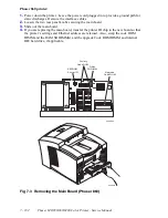
Phaser 840/850/860/8200 Color Printer - Service Manual
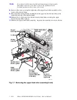
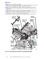
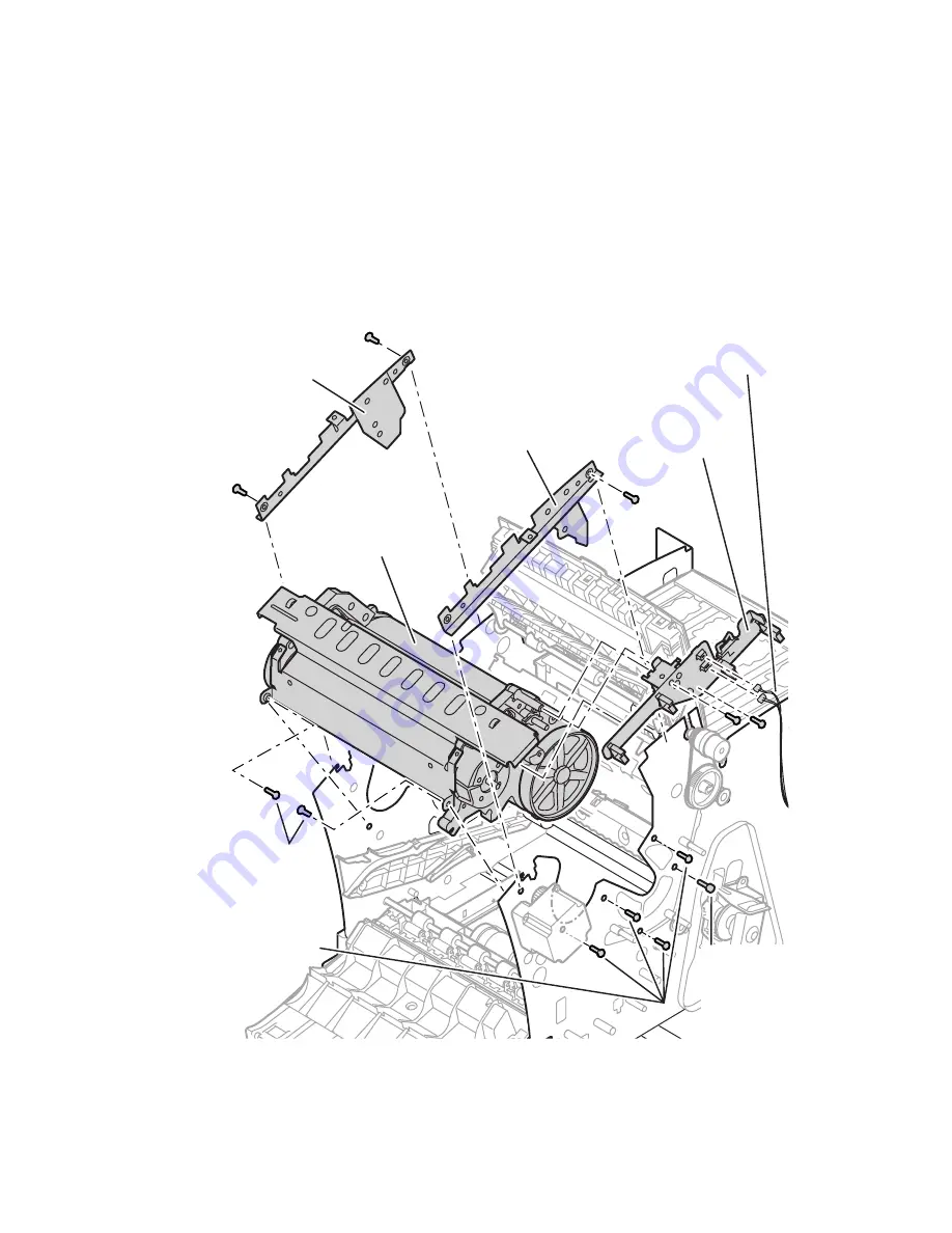
Right side
15.
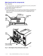
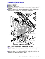
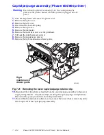
Remove the y-axis belt drive assembly.
16.
Disconnect the wiring harnesses leading to the transfix solenoid bracket. Remove the
three screws securing the bracket in place and remove the bracket.
17.
Remove the left and right frame bridges. Each is held in place with two screws.
18.
Remove the two screws securing the front of the drum/transfix frame to the inside
printer frame.
19.
Remove the five screws securing the left side of the drum/transfix assembly to the
print engine. Note that one screw is removed with a 3/32” hex key.
20.
Remove the five screws securing the right side of the drum/transfix assembly to the
print engine. Note that one screw is removed with a hex key.
21.
Carefully, lift and remove the drum/transfix assembly. Protect the drum surface.
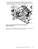
Fig 7-10 Removing the drum/transfix assembly (right side)
840-4-20
Left frame
bridge
Remove
hex
screw
Remove 4
screws
Remove
2 inside
screws
Right frame
bridge
Wiring
harnesses
Transfix
solenoid
bracket
Drum transfix
assembly
Summary of Contents for Phaser 840
Page 2: ......
Page 12: ...vi Phaser 840 850 860 8200 Color Printer Service Manual ...
Page 52: ...1 36 Phaser 840 850 860 8200 Color Printer Service Manual ...
Page 88: ...2 72 Phaser 840 850 860 8200 Color Printer Service Manual Blank Page ...
Page 134: ...3 118 Phaser 840 850 860 8200 Color Printer Service Manual ...
Page 174: ...4 158 Phaser 840 850 860 8200 Color Printer Service Manual ...
Page 188: ......
Page 250: ...8 234 Phaser 840 850 860 8200 Color Printer Service Manual ...
Page 286: ...270 Phaser 840 850 860 8200 Color Printer Service Manual ...
Page 287: ...071 0723 00 ...


