
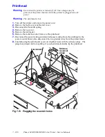


Removal and Replacement Procedures
7 - 197
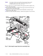
9.
If you use the removal tool, rotate the removal tool’s plastic leg into its up position.
Slide the removal tool’s standoff locks inward.
10.
Place a sheet of transparency film or 10 sheets of paper between the printhead and the
drum to protect the drum surface.
11.
If you use the printhead removal tool, carefully, lower it onto the printhead. Rotate
the process motor to tilt the printhead forward about 2.5 cm (1 inch).
12.
If you use the removal tool, slide the standoff locks outward to secure the tool to the
printhead. Loosen the two mounting screws securing the printhead in place.
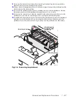
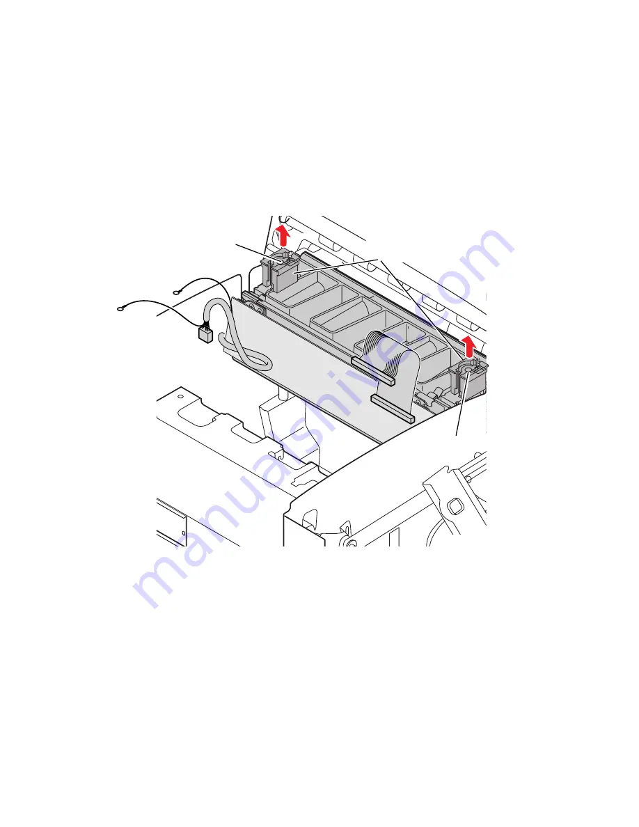
13.
Carefully lift on the plastic posts at each end of the printhead to remove the printhead
and place it on a flat surface. If you are using the removal tool, lift and remove the
printhead. Lower the removal tool’s leg to safely rest the printhead on a flat surface.
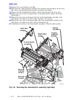
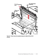
Fig 7-16 Removing the printhead
Lift printhead by
the plastic posts
at each end
840-4-89
Mounting screw
Mounting screw
Summary of Contents for Phaser 840
Page 2: ......
Page 12: ...vi Phaser 840 850 860 8200 Color Printer Service Manual ...
Page 52: ...1 36 Phaser 840 850 860 8200 Color Printer Service Manual ...
Page 88: ...2 72 Phaser 840 850 860 8200 Color Printer Service Manual Blank Page ...
Page 134: ...3 118 Phaser 840 850 860 8200 Color Printer Service Manual ...
Page 174: ...4 158 Phaser 840 850 860 8200 Color Printer Service Manual ...
Page 188: ......
Page 250: ...8 234 Phaser 840 850 860 8200 Color Printer Service Manual ...
Page 286: ...270 Phaser 840 850 860 8200 Color Printer Service Manual ...
Page 287: ...071 0723 00 ...