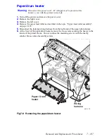

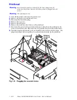


Removal and Replacement Procedures
7 - 199
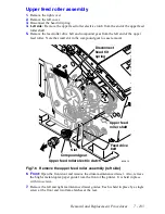
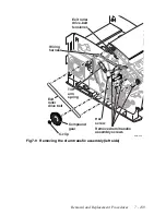
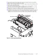
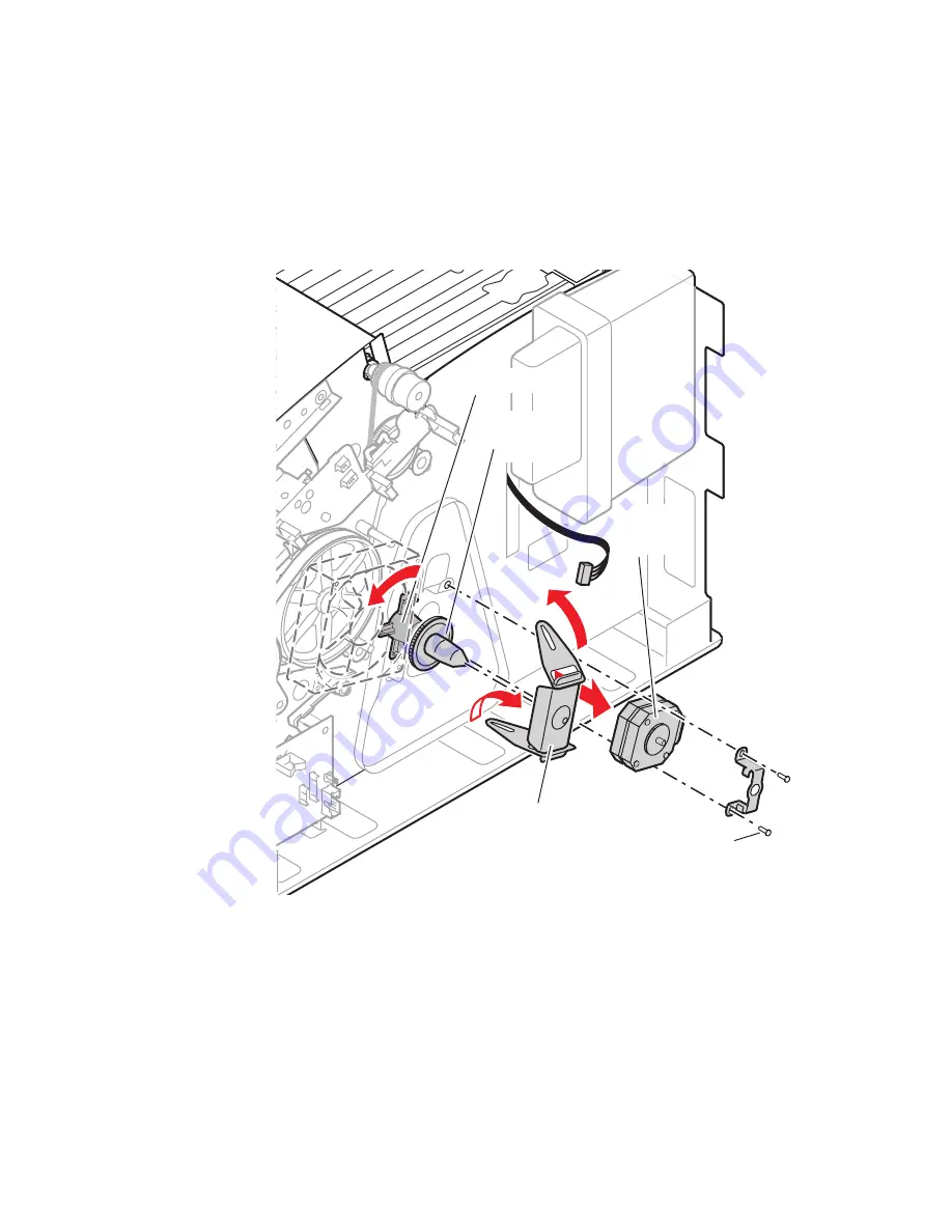
X-axis motor and drive assembly
1.
Remove the right cover.
2.
Remove the left cover. Disconnect the head-tilt spring.
3.
Disconnect the X-axis motor wiring harness at the x-axis motor.
4.
Remove the screws securing the X-axis motor and bracket in place.
5.
Rotate the black, plastic retainer counterclockwise.
6.
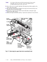
Lift up the bottom portion of the X-axis drive yoke. Lift up the yoke and remove the
upper portion of the yoke.
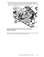
7.
Rotate the X-axis cone gear counterclockwise to remove it from the X-axis shaft.
For reassembly, apply a
small
amount of grease on the tip of the nose cone. Apply a
small
amount, 3 dabs, on the threads of the X-axis shaft. Be sure to rotate the black, plastic
retainer so its end locks the yoke in position. Perform the "X-axis scale adjustment", on
page 4-149.
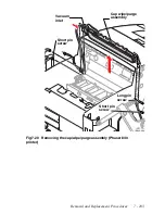
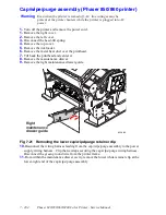
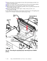
Fig 7-17 Removing the x-axis motor and drive assembly
840-4-22
X-axis drive yoke
(remove bottom first)
Phaser 840
only
Retainer
Cone
gear
X-axis
motor
Summary of Contents for Phaser 840
Page 2: ......
Page 12: ...vi Phaser 840 850 860 8200 Color Printer Service Manual ...
Page 52: ...1 36 Phaser 840 850 860 8200 Color Printer Service Manual ...
Page 88: ...2 72 Phaser 840 850 860 8200 Color Printer Service Manual Blank Page ...
Page 134: ...3 118 Phaser 840 850 860 8200 Color Printer Service Manual ...
Page 174: ...4 158 Phaser 840 850 860 8200 Color Printer Service Manual ...
Page 188: ......
Page 250: ...8 234 Phaser 840 850 860 8200 Color Printer Service Manual ...
Page 286: ...270 Phaser 840 850 860 8200 Color Printer Service Manual ...
Page 287: ...071 0723 00 ...