


General Information
1 - 13
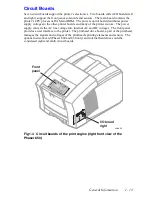
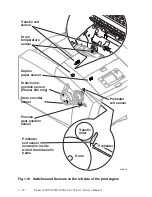
Circuit Boards
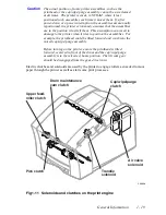
Seven circuit boards support the printer’s electronics. Two boards, called I/O boards (left
and right), support the front panel, solenoids and sensors. The main board contains the
printer’s CPU processor, RAM and ROM. The power control board distributes power
supply voltages to the other printer boards and many of the printer motors. The power
supply converts the AC line voltage into internal AC and DC voltages. The front panel
provides a user interface to the printer. The printhead drive board, a part of the printhead,
manages the signals and voltages of the printhead’s printing elements and sensors. The
optional network card (Phaser 840 and 850 only) and internal hard drive could be
considered eight and ninth circuit boards.
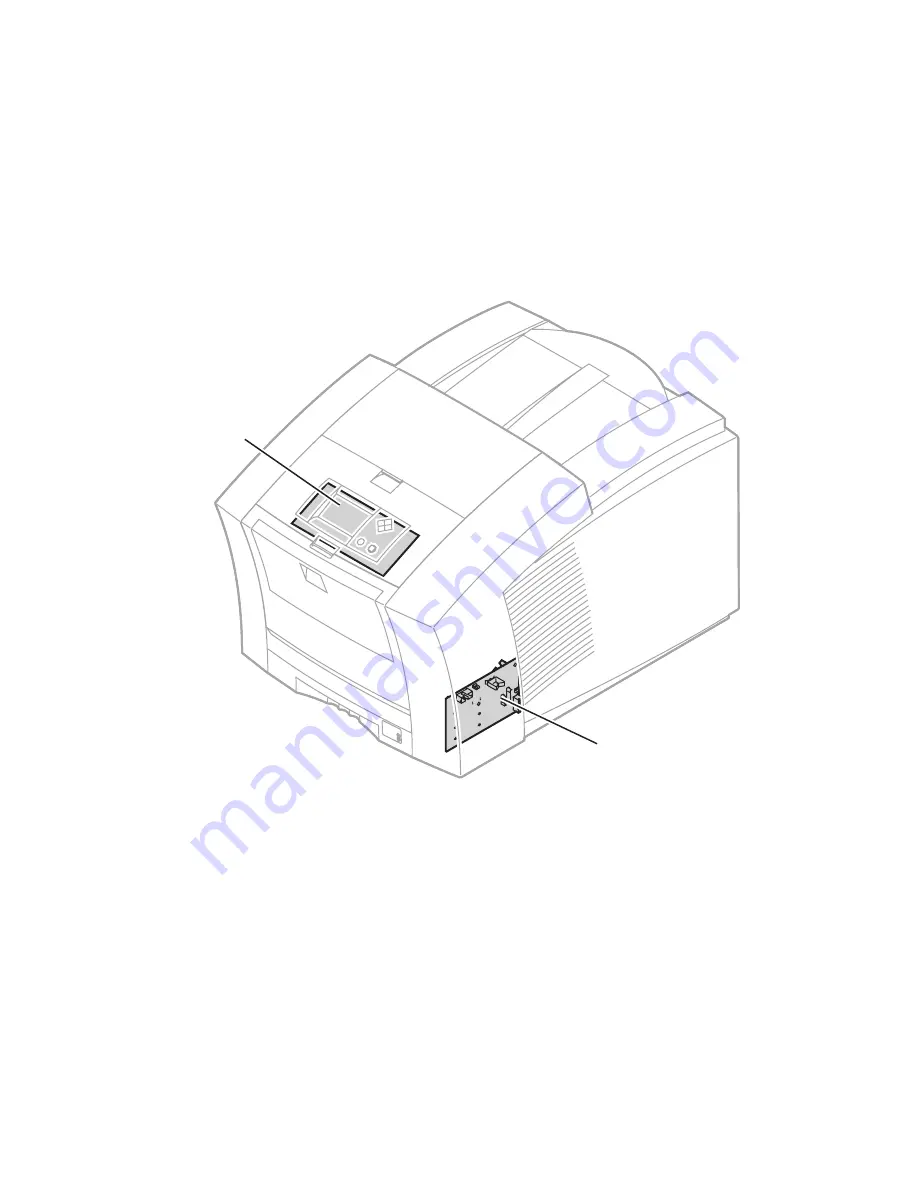
Fig 1-4 Circuit boards of the print engine (right front view of the
Phaser 850)
0388-03
I/O board
right
Front
panel
Summary of Contents for Phaser 840
Page 2: ......
Page 12: ...vi Phaser 840 850 860 8200 Color Printer Service Manual ...
Page 52: ...1 36 Phaser 840 850 860 8200 Color Printer Service Manual ...
Page 88: ...2 72 Phaser 840 850 860 8200 Color Printer Service Manual Blank Page ...
Page 134: ...3 118 Phaser 840 850 860 8200 Color Printer Service Manual ...
Page 174: ...4 158 Phaser 840 850 860 8200 Color Printer Service Manual ...
Page 188: ......
Page 250: ...8 234 Phaser 840 850 860 8200 Color Printer Service Manual ...
Page 286: ...270 Phaser 840 850 860 8200 Color Printer Service Manual ...
Page 287: ...071 0723 00 ...


