03/02
Level 2 Troubleshooting
WorkCentre Pro 423/428
2-137
CHAPTER 2 TROUBLESHOOTING
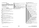
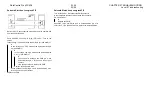
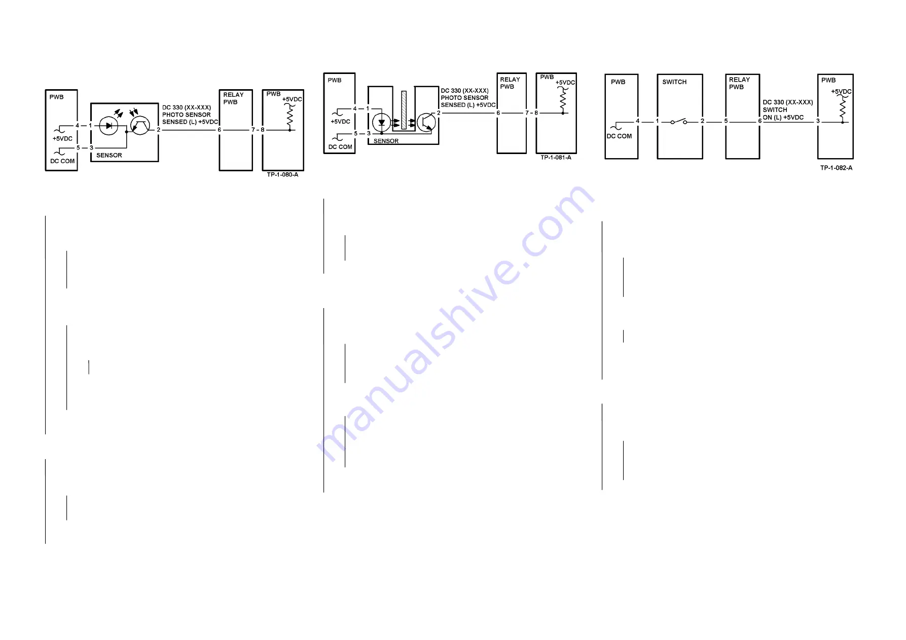
2.3.6 General-purpose FIP
Reflection Sensor fault FIP
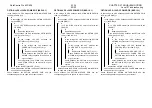
Enter Chain XX Func XXX in Diag (CE) mode. Block the sensor
with blank paper. Is LOW displayed?
Y
N
Is the v5 VDC between the Sensor pin 2 (+) and
GND(-)?
Y
N
Check between the Sensor pin 2 and PWB pin 8 for
an open wire or poor contact. If no problem is found,
replace the PWB.
Is the v5 VDC between the Sensor pin 1(+) and
GND(-)?
Y
N
Is the v5 VDC between the PWB pin 4(+)
andpin 5(-)?
Y
N
Replace the PWB.
Check the wires between the PWB pin 4 and Sensor
pin 1 and between the PWB pin 5 and Sensor pin 3
for an open wire or poor contact.
Check the sensor for contamination or installation fault. If
no problem is found, replace the sensor.
Remove the blank paper from the sensor. Is HIGH displayed?
Y
N
Disconnect the sensor connector.
Does the display change to HIGH?
Y
N
Check the circuit from sensor pin 2 to PWB pin 8 for a
short circuit. If no problem is found, replace the PWB.
Check the sensor installation and external lighting. If no
problem is found, replace the sensor.
Check the sensor installation. If no problem is found, replace the
Sensor.
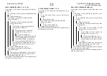
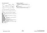
Transmission Sensor fault FIP
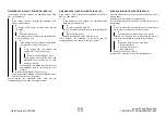
Enter Chain XX Func XXX in Diag (CE) mode. Block the sensor.
Is HIGH displayed?
Y
N
Disconnect the sensor connector.
Does the display change to HIGH?
Y
N
Check the circuit from sensor pin 2 to PWB pin 8 for a
short circuit. If no problem is found, replace the PWB.
Replace the sensor.
Remove the block from the optical path of the sensor.
Does the display change to LOW?
Y
N
Is the v5 VDC between the sensor pin 2 (+) and
GND(-)?
Y
N
Check between the sensor pin 2 and PWB pin 8 for
an open wire or poor contact. If no problem is found,
replace the PWB.
Is the v5 VDC between the sensor pin 1(+) and pin
3(-)?
Y
N
Check the wires between the PWB pin 4 and sensor
pin 1and between the PWB pin 5 and sensor pin 3 for
an open wire or poor contact. If no problem is found,
replace the PWB.
Check the sensor for contamination or installation fault. If
no problem is found, replace the sensor.
Check the sensor for an installation problem and the actuator for
a bending or operation error.
If no problem is found, replace the sensor.
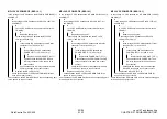
Switch (Normal Open) fault FIP
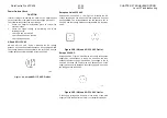
Enter Chain XX Func XXX in Diag (CE) mode. Turn on the
switch.
Does the display change to LOW?
Y
N
Is the v5 VDC between the swith pin 2 (+) and
GND(-)?
Y
N
Check between the Switch pin 2 and PWB pin 3 for an
open wire or poor contact. If no problem is found,
replace the PWB.
When the switch is on, is the v5 VDC between the
Switch pin 1(+) and GND?
Y
N
Replace the switch.
Check between the PWB pin 4 and switch pin 1 for an open
wire or poor contact. If no problem is found, replace the
PWB.
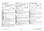
Turn off the switch. Does the display change to HIGH?
Y
N
Disconnect the switch connector.
Is the display still HIGH?
Y
N
Check the circuit from the switch pin 2 to PWB pin 3
for a short circuit. If no problem is found, replace the
PWB.
Replace the switch.
Check the switch installation. If no problem is found, replace the
switch.
Summary of Contents for WorkCentre Pro 423
Page 2: ......
Page 3: ...WorkCentre Pro 423 428 6HUYLFH 0DQXDO...
Page 6: ......
Page 8: ......
Page 9: ...INTRODUCTION...
Page 10: ......
Page 24: ...WorkCentre 423 428 03 02 INTRODUCTION 14 7 Translation of Warnings...
Page 25: ...CHAPTER 1 SERVICE CALL PROCEDURE...
Page 26: ......
Page 28: ...WorkCentre Pro 423 428 1 2 CHAPTER 1 SERVICE CALL PROCEDURE 03 02 1 1 Trimming...
Page 31: ...CHAPTER 2 TROUBLESHOOTING...
Page 32: ......
Page 76: ...WorkCentre Pro 423 428 2 44 CHAPTER 2 TROUBLESHOOTING 03 02 2 3 Level 2 Troubleshooting...
Page 243: ...CHAPTER 3 IMAGE QUALITY TROUBLESHOOTING...
Page 244: ......
Page 273: ...CHAPTER 4 DISASSEMBLY ASSEMBLY AND ADJUSTMENT...
Page 274: ......
Page 329: ...CHAPTER 5 PARTS LIST...
Page 330: ......
Page 415: ...03 02 5 2 Parts List WorkCentre Pro 423 428 5 85 CHAPTER 5 PARTS LIST...
Page 416: ...CHAPTER 6 GENERAL...
Page 417: ......
Page 456: ...CHAPTER 7 ELECTRICAL WIRING DIAGRAMS...
Page 457: ......
Page 476: ...CHAPTER 8 ACCESSORIES...
Page 477: ......
Page 535: ...WorkCentre Pro 423 428 8 58 CHAPTER 8 ACCESSORIES 03 02 8 22 Stamp Kit Red...
Page 536: ...CHAPTER 9 BSD Block Schematic Diagram...
Page 537: ......
Page 541: ......
Page 542: ......
Page 543: ......
Page 544: ......
Page 545: ......
Page 546: ......
Page 547: ......
Page 548: ......
Page 549: ......
Page 550: ......
Page 551: ......
Page 552: ......
Page 553: ......
Page 554: ......
Page 555: ......
Page 556: ......
Page 557: ......
Page 558: ......
Page 559: ......
Page 560: ......
Page 561: ......
Page 562: ......
Page 563: ......
Page 564: ......
Page 565: ......
Page 566: ......
Page 567: ......
Page 568: ......
Page 569: ......
Page 570: ......
Page 571: ......
Page 572: ......
Page 573: ......
Page 574: ......
Page 575: ......
Page 576: ......
Page 577: ......
Page 578: ......
Page 579: ......
Page 580: ......
Page 581: ......
Page 582: ......
Page 583: ......
Page 584: ......
Page 585: ......
Page 586: ......
Page 587: ......
Page 588: ......
Page 589: ......
Page 590: ......
Page 591: ......
Page 592: ......
Page 593: ......
Page 594: ......
Page 595: ......
Page 596: ......
Page 597: ......
Page 598: ......
Page 599: ......
Page 600: ......
Page 601: ......
Page 602: ......
Page 603: ......
Page 604: ......
Page 605: ......
Page 606: ......
Page 607: ......
Page 608: ......
Page 609: ......
Page 610: ......
Page 611: ......
Page 612: ......
Page 613: ......
Page 614: ......
Page 615: ......
Page 616: ......
Page 617: ......
Page 618: ......
Page 619: ......


