WorkCentre Pro 423/428
2-184
CHAPTER 2 TROUBLESHOOTING
03/02
How to use the Diagnostic C/E Mode
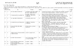
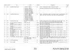
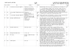
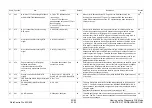
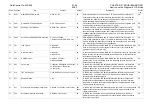
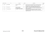
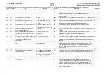
2.4.9.12 Fax System Data
*:Same feature with Channel 1 **:Same feature with Channel 1 & 2 ***:Same feature with Channel 1, 2, and 3
(Channel 1:Chain code 157, Channel 2:Chain code 257, Channel 3:Chain code 357) When there are two defaults (ex. 10(0A)), the value outside the parentheses is decimal and that inside is
hexadecimal.
Chain Function
Item
Content
Default
Description
Access
by
57
1**
Line Type (NCU0: Outside Line)
0:PSTN(Public Switched Telephone
Network) 1:PBX(Private Branch
Exchange) 2 = Direct Line
00
This data sets a line type for the main unit connection line (NCU0). When NTT
is set, busy tone detection is enabled. If 2= Direct Line is set, a 1300 Hz
signal is sent to the line when a single numeric key is pressed.
User
57
2**
Dial Type Channel 0 for Outside Line
0:PB(DTMF) 1:DP(10PPS)
2:DP(20PPS)
00
This data sets a dial type for signal send to the main unit connection line
(NCU0). Set PB for pushbutton signals and 20PPS or 10PPS for dial pulse
signals. Setting a wrong dial type always results in busy processing.
User
57
3**
Line Type (NCU0: Extension Line)
0:PSTN 1:PBX 2:Direct Line
01
Sets up a type of the line when the NCU0 is replaced with the optional
“Ext/Outside line NCU”. Press the “Extension” button on the Control Panel to
connect this line. The parameter (FUNC.No.) indicates “Function
No.001”(Function=001).
User
57
4**
Dial Type Channel 0 for Extension Line
0:PB(DTMF) 1:DP(10PPS)
2:DP(20PPS)
00
Sets up a type of the line when the NCU0 is replaced with the optional
“Ext/Outside line NCU”. The parameter indicates Chain=057
and
Function=002(Dial type), and when a wrong dial is set up, all signals will be
processed as “Busy”.
User
57
5
Restriction of Dial Type Change
0: Do not restrict 1: Restrict
00
Restriction of Dial Type Change for 57-2 and 4
CE
57
10
Pause time
0 to 255 sec.
03
For origination to NCU connected line (NTT/PBX), dialing stops for the set
time. A pause is inserted into the remote party’s telephone number
information for the user to hear the tone and the second dial tone. For ISDN,
any pause before “/” is ignored. Once “/” has appeared, the operation is the
same as in the above NCU case.
User
57
11
Independent communication intervals at
broadcast operation
3-255 sec (1 setp=1 sec)??
08
This data prescribes intervals between independent communication sessions
in broadcast. If frequent relay broadcast instructions are anticipated and the
general communication volume is large, set a greater value to extend the line
free time for longer reception because relay broadcast results do not return
easily.
User
57
12
Number of resend operations
0 to 5 times(5) (1step=1 resend)
(0: No resend operated)
03
When a transmission ends as invalid at auto send operation due to abnormal
line condition or failure at the remote terminal, release the line once, then
resend the page not transmitted. The data specifies the number of resend
operations to be dialed for.
User
57
13
Enable/Disable Received Document
Sorting by Line Services
0: Disable 1: Enable
00
57
14
Enable/Disable Received Document
Sorting by Lines
0: Disable 1: Enable
00
Summary of Contents for WorkCentre Pro 423
Page 2: ......
Page 3: ...WorkCentre Pro 423 428 6HUYLFH 0DQXDO...
Page 6: ......
Page 8: ......
Page 9: ...INTRODUCTION...
Page 10: ......
Page 24: ...WorkCentre 423 428 03 02 INTRODUCTION 14 7 Translation of Warnings...
Page 25: ...CHAPTER 1 SERVICE CALL PROCEDURE...
Page 26: ......
Page 28: ...WorkCentre Pro 423 428 1 2 CHAPTER 1 SERVICE CALL PROCEDURE 03 02 1 1 Trimming...
Page 31: ...CHAPTER 2 TROUBLESHOOTING...
Page 32: ......
Page 76: ...WorkCentre Pro 423 428 2 44 CHAPTER 2 TROUBLESHOOTING 03 02 2 3 Level 2 Troubleshooting...
Page 243: ...CHAPTER 3 IMAGE QUALITY TROUBLESHOOTING...
Page 244: ......
Page 273: ...CHAPTER 4 DISASSEMBLY ASSEMBLY AND ADJUSTMENT...
Page 274: ......
Page 329: ...CHAPTER 5 PARTS LIST...
Page 330: ......
Page 415: ...03 02 5 2 Parts List WorkCentre Pro 423 428 5 85 CHAPTER 5 PARTS LIST...
Page 416: ...CHAPTER 6 GENERAL...
Page 417: ......
Page 456: ...CHAPTER 7 ELECTRICAL WIRING DIAGRAMS...
Page 457: ......
Page 476: ...CHAPTER 8 ACCESSORIES...
Page 477: ......
Page 535: ...WorkCentre Pro 423 428 8 58 CHAPTER 8 ACCESSORIES 03 02 8 22 Stamp Kit Red...
Page 536: ...CHAPTER 9 BSD Block Schematic Diagram...
Page 537: ......
Page 541: ......
Page 542: ......
Page 543: ......
Page 544: ......
Page 545: ......
Page 546: ......
Page 547: ......
Page 548: ......
Page 549: ......
Page 550: ......
Page 551: ......
Page 552: ......
Page 553: ......
Page 554: ......
Page 555: ......
Page 556: ......
Page 557: ......
Page 558: ......
Page 559: ......
Page 560: ......
Page 561: ......
Page 562: ......
Page 563: ......
Page 564: ......
Page 565: ......
Page 566: ......
Page 567: ......
Page 568: ......
Page 569: ......
Page 570: ......
Page 571: ......
Page 572: ......
Page 573: ......
Page 574: ......
Page 575: ......
Page 576: ......
Page 577: ......
Page 578: ......
Page 579: ......
Page 580: ......
Page 581: ......
Page 582: ......
Page 583: ......
Page 584: ......
Page 585: ......
Page 586: ......
Page 587: ......
Page 588: ......
Page 589: ......
Page 590: ......
Page 591: ......
Page 592: ......
Page 593: ......
Page 594: ......
Page 595: ......
Page 596: ......
Page 597: ......
Page 598: ......
Page 599: ......
Page 600: ......
Page 601: ......
Page 602: ......
Page 603: ......
Page 604: ......
Page 605: ......
Page 606: ......
Page 607: ......
Page 608: ......
Page 609: ......
Page 610: ......
Page 611: ......
Page 612: ......
Page 613: ......
Page 614: ......
Page 615: ......
Page 616: ......
Page 617: ......
Page 618: ......
Page 619: ......

