03/02
How to use the Diagnostic C/E Mode
WorkCentre Pro 423/428
2-195
CHAPTER 2 TROUBLESHOOTING
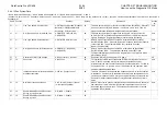
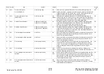
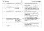
Chain Function
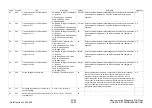
Item
Content
Default
Description
Access
by
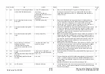
57
663
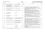
Number of FTTs Resulting in Fall Back
at G3M 9600/7200/4800/2400bps
0: Twice FTT fallbacks at all
frequencies
1: Once FTT Fall Back at
4800/2400bps only (twice FTT Fall
Back at others)
2: Once FTT Fall Back at all
frequencies
00
When error is detected by the TCF signal or the EQM data check, the
receiving terminal sends FTT signal. This data specifies how the modem
speed will be reduced based on the FTT signal detected when the signal is
sent by Main unit.
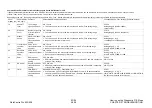
CE
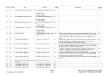
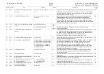
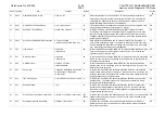
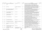
57
670
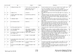
No. of consecutive lines for sending
RTN signal
0 to 255line(1step=1line)
05
When error is identified in the image data received, this data specifies the
number of consecutive error lines to determine which signal should be send
back, the MCF signal or RTN signal. Some transmitters may falls back
whenever they receive the RTN signal or send back the same image data. In
such a case, set up a greater number for consecutive error lines.
CE
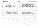
57
671
Area rate allowed for sending RTN
signal
0 to 100%(1step=1%)
05
When error is identified in the image data received, this data specifies the rate
of error area to determine which signal should be send back, the MCF signal
or RTN signal. Some transmitters may falls back whenever they receive the
RTN signal or send back the same image data. In such a case, set up a
greater number for the area rate.
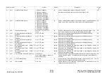
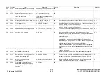
CE
57
672
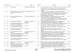
Area rate allowed for sending RTP
signal
0 to 10%(1step=0.1%)
05
When error is identified in the image data received, and the level generated is
between the MCF signal and RTN signal, the RTP signal will be sent back for
conducting the training again. This data set as the standard by specifying the
error area rate. Some transmitters may falls back whenever they receive the
RTN signal or send back the same image data. In such a case, set up a
greater number for the area rate.
CE
57
673
Page processing for RTN signal
detected at send side.
If the transmitter receives RTN,
continuation is determined from this
data.
1: Suspend transmission (This
sentence is resent.)
00
Determines how to handle thr transmission page that detected the RTN signal
sent from the receiving terminal. Some of the receiving terminals may appear
to send back the RTN signal with the severe error rate, but the machine
recognizes the error status which can be overlooked by human eyes. It is
necessary, therefore, to understand the RTN process status of the remote
terminal when you change the setup.
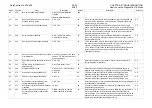
CE
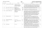
57
676
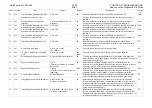
Storing error codes for EOR/RTN
signals
0 :Do not store 1 :Store RTN 2:
Store EOR 3: Store EOR and RTN
02
Determines whether or not to store error when the EOR/RTN signals are sent
or received.
CE
57
680
FSK Detection before Image Information
Reception
0:No 1:Yes
01
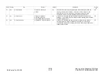
57
690
ECM capability (Auto Error Resend
Function)
0:Off 1:On
01
This data determines the Error Correction Mode capability as recommended
by ITU-T. The ECM capability bit data of the NSF/NSC/NSS/DIS/DTC/ DCS
signal, based on the setup data, changes and informs the remote terminal of it
using the signal.
Individually reflectable on each speed dial (refer to page 2-207)
CE
57
691
ECM Frame Size
0:256bytes 1:64kbytes
00
This data specifies the frame size of the send side when ECM communication
is made. The ITU-T recommendation specifies to use 64 and 256 but the data
has never been changed.
CE
Summary of Contents for WorkCentre Pro 423
Page 2: ......
Page 3: ...WorkCentre Pro 423 428 6HUYLFH 0DQXDO...
Page 6: ......
Page 8: ......
Page 9: ...INTRODUCTION...
Page 10: ......
Page 24: ...WorkCentre 423 428 03 02 INTRODUCTION 14 7 Translation of Warnings...
Page 25: ...CHAPTER 1 SERVICE CALL PROCEDURE...
Page 26: ......
Page 28: ...WorkCentre Pro 423 428 1 2 CHAPTER 1 SERVICE CALL PROCEDURE 03 02 1 1 Trimming...
Page 31: ...CHAPTER 2 TROUBLESHOOTING...
Page 32: ......
Page 76: ...WorkCentre Pro 423 428 2 44 CHAPTER 2 TROUBLESHOOTING 03 02 2 3 Level 2 Troubleshooting...
Page 243: ...CHAPTER 3 IMAGE QUALITY TROUBLESHOOTING...
Page 244: ......
Page 273: ...CHAPTER 4 DISASSEMBLY ASSEMBLY AND ADJUSTMENT...
Page 274: ......
Page 329: ...CHAPTER 5 PARTS LIST...
Page 330: ......
Page 415: ...03 02 5 2 Parts List WorkCentre Pro 423 428 5 85 CHAPTER 5 PARTS LIST...
Page 416: ...CHAPTER 6 GENERAL...
Page 417: ......
Page 456: ...CHAPTER 7 ELECTRICAL WIRING DIAGRAMS...
Page 457: ......
Page 476: ...CHAPTER 8 ACCESSORIES...
Page 477: ......
Page 535: ...WorkCentre Pro 423 428 8 58 CHAPTER 8 ACCESSORIES 03 02 8 22 Stamp Kit Red...
Page 536: ...CHAPTER 9 BSD Block Schematic Diagram...
Page 537: ......
Page 541: ......
Page 542: ......
Page 543: ......
Page 544: ......
Page 545: ......
Page 546: ......
Page 547: ......
Page 548: ......
Page 549: ......
Page 550: ......
Page 551: ......
Page 552: ......
Page 553: ......
Page 554: ......
Page 555: ......
Page 556: ......
Page 557: ......
Page 558: ......
Page 559: ......
Page 560: ......
Page 561: ......
Page 562: ......
Page 563: ......
Page 564: ......
Page 565: ......
Page 566: ......
Page 567: ......
Page 568: ......
Page 569: ......
Page 570: ......
Page 571: ......
Page 572: ......
Page 573: ......
Page 574: ......
Page 575: ......
Page 576: ......
Page 577: ......
Page 578: ......
Page 579: ......
Page 580: ......
Page 581: ......
Page 582: ......
Page 583: ......
Page 584: ......
Page 585: ......
Page 586: ......
Page 587: ......
Page 588: ......
Page 589: ......
Page 590: ......
Page 591: ......
Page 592: ......
Page 593: ......
Page 594: ......
Page 595: ......
Page 596: ......
Page 597: ......
Page 598: ......
Page 599: ......
Page 600: ......
Page 601: ......
Page 602: ......
Page 603: ......
Page 604: ......
Page 605: ......
Page 606: ......
Page 607: ......
Page 608: ......
Page 609: ......
Page 610: ......
Page 611: ......
Page 612: ......
Page 613: ......
Page 614: ......
Page 615: ......
Page 616: ......
Page 617: ......
Page 618: ......
Page 619: ......

