WorkCentre Pro 423/428
2-196
CHAPTER 2 TROUBLESHOOTING
03/02
How to use the Diagnostic C/E Mode
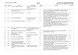
Chain Function
Item
Content
Default
Description
Access
by
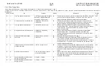
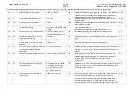
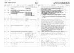
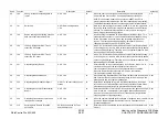
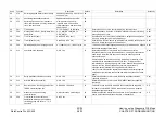
57
692**
G3M0 ECM CTC Number
0:000 to 7:111
05
Determines whether or not to send the CTC signal (including the fall back
data) after sending the identical frame the specific times. By increasing the
setup data, the signal will be send by the same modem speed on the line
where the failure occurred which is not practical.
CE
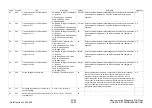
57
693**
G3M0 ECM CTC Speed Down
0:Off 1: Speed down.
01
The data should not be changed as the transmission can be completed more
often by letting the fall back occur at the CTC signal.
CE
57
694**
Sending CTC at 2400bps
0:Send 1:Do not send
00
In the G3 models, a modem with 2400bps or higher?? speed is not used.
Possibility of completing communication is higher by releasing the line once,
then transmitting signals using the newly supplied line, rather than sending
2400bps repeatedly using an inferior quality line. As a result, the data should
normally be not changed.
CE
57
696**
Action after G3M0 ECM EOR detection
0: To be continued
1: Release line for EOR-EOP only
01
EOR signal can be detected when an extremely inferior line is supplied. In
such a case, possibility is higher to complete by releasing the line, then using
a newly supplied line rather than continuing communication using the existing
line. Accordingly, the data need not be changed.
CE
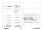
57
791
Link modulo
0:Modulo 8
1:Modulo 128
00
In the communication using the ISDN line, this data specifies the modulo type
used for monitoring the number system of data link layer (for checking the
signal delivered, or received, etc.).
CE
57
801
Network modulo
0:Modulo 8
1:Modulo 128
00
In the communication using the ISDN line, this data determines the applicable
area where the numbers can be added to the data packet, so that the network
layer cannot be overflowed
CE
57
802
CSDN Protocol
0:X21PLP 1:T70null
2:IS8208modified
02
In the communication using the ISDN-CDDN line, this data determines the
protocol used for communicating to the line exchange network. Basically, the
data needs not be changed.
CE
57
803
Packet size
7:128bytes 8:256bytes 9:512bytes
10:1024bytes 11:2048bytes
12:4097bytes
11
In the G4 communication, this data determines the maximum user data field
length of data packet for the network layer. When a small size is selected, the
data size transmitted per packet will be smaller and a longer transmission time
will result depending on the data volume.
CE
57
810
TDT blocking size
7:128 8:256 9:512 10:1024 11:2049
11
In the G4 communication, this data determines the data blocking size at the
transport layer. The data must be set to “2048” to be accessible to the G4
facsimile communication network.
CE
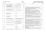
57
820
Session window
1 to 3
03
In the G4 communication, this data determines the number of consecutive
transmission of data package for the session layer. As the value is smaller,
the number of delivery checks for data packages will be greater and a longer
communication time will result.
CE
57
821
Wireless communication monitor timer
0:Infinite 1: to 255sec (1sec=1step)
60=
60sec
In the G4 communication, this data sets up time to monitor non communication
status for the session layer protocol. The data need not be changed unless
otherwise instructed.
CE
57
822
Exceptional process of sessions
0:Session 1:Document
00
In the G4 communication, when communication failure occurs, this data
determines which layer should be moved to the disabled status, the session
layer or document layer.
CE
Summary of Contents for WorkCentre Pro 423
Page 2: ......
Page 3: ...WorkCentre Pro 423 428 6HUYLFH 0DQXDO...
Page 6: ......
Page 8: ......
Page 9: ...INTRODUCTION...
Page 10: ......
Page 24: ...WorkCentre 423 428 03 02 INTRODUCTION 14 7 Translation of Warnings...
Page 25: ...CHAPTER 1 SERVICE CALL PROCEDURE...
Page 26: ......
Page 28: ...WorkCentre Pro 423 428 1 2 CHAPTER 1 SERVICE CALL PROCEDURE 03 02 1 1 Trimming...
Page 31: ...CHAPTER 2 TROUBLESHOOTING...
Page 32: ......
Page 76: ...WorkCentre Pro 423 428 2 44 CHAPTER 2 TROUBLESHOOTING 03 02 2 3 Level 2 Troubleshooting...
Page 243: ...CHAPTER 3 IMAGE QUALITY TROUBLESHOOTING...
Page 244: ......
Page 273: ...CHAPTER 4 DISASSEMBLY ASSEMBLY AND ADJUSTMENT...
Page 274: ......
Page 329: ...CHAPTER 5 PARTS LIST...
Page 330: ......
Page 415: ...03 02 5 2 Parts List WorkCentre Pro 423 428 5 85 CHAPTER 5 PARTS LIST...
Page 416: ...CHAPTER 6 GENERAL...
Page 417: ......
Page 456: ...CHAPTER 7 ELECTRICAL WIRING DIAGRAMS...
Page 457: ......
Page 476: ...CHAPTER 8 ACCESSORIES...
Page 477: ......
Page 535: ...WorkCentre Pro 423 428 8 58 CHAPTER 8 ACCESSORIES 03 02 8 22 Stamp Kit Red...
Page 536: ...CHAPTER 9 BSD Block Schematic Diagram...
Page 537: ......
Page 541: ......
Page 542: ......
Page 543: ......
Page 544: ......
Page 545: ......
Page 546: ......
Page 547: ......
Page 548: ......
Page 549: ......
Page 550: ......
Page 551: ......
Page 552: ......
Page 553: ......
Page 554: ......
Page 555: ......
Page 556: ......
Page 557: ......
Page 558: ......
Page 559: ......
Page 560: ......
Page 561: ......
Page 562: ......
Page 563: ......
Page 564: ......
Page 565: ......
Page 566: ......
Page 567: ......
Page 568: ......
Page 569: ......
Page 570: ......
Page 571: ......
Page 572: ......
Page 573: ......
Page 574: ......
Page 575: ......
Page 576: ......
Page 577: ......
Page 578: ......
Page 579: ......
Page 580: ......
Page 581: ......
Page 582: ......
Page 583: ......
Page 584: ......
Page 585: ......
Page 586: ......
Page 587: ......
Page 588: ......
Page 589: ......
Page 590: ......
Page 591: ......
Page 592: ......
Page 593: ......
Page 594: ......
Page 595: ......
Page 596: ......
Page 597: ......
Page 598: ......
Page 599: ......
Page 600: ......
Page 601: ......
Page 602: ......
Page 603: ......
Page 604: ......
Page 605: ......
Page 606: ......
Page 607: ......
Page 608: ......
Page 609: ......
Page 610: ......
Page 611: ......
Page 612: ......
Page 613: ......
Page 614: ......
Page 615: ......
Page 616: ......
Page 617: ......
Page 618: ......
Page 619: ......

