03/02
4.2 Disassembly and Assembly
WorkCentre Pro 432/428
4-5
CHAPTER 4 DISASSEMBLY/ASSEMBLY AND ADJUSTMENT
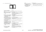
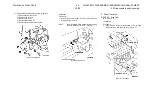
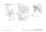
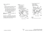
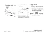
2. Install the Size Cam while aligning its hole with the
U groove of the Tray. (Figure-2)
1) Install the Size Cam.
2) Insert the Lock Pin.
(Figure-2) j0hn4202
REP 2.4.1 R/H Chute Assembly
Ref. PL: PL2.4
Removal
On printer or Fax-equipped machines, ensure that
outstanding jobs have cleared before servicing or
interrupting the power to the machine as follows:.
•
FAX equipped machines: Ensure that the “Job in
Memory” indicator on the control panel goes out.
Press “Job Status:Stop” button and confirm that the
job has cleared from the “Current Jobs” folder.
•
Printer machines: Ensure that “Ready to print or
fax” is indicated on the printer control panel.
WARNING
Switch off the machine and disconnect the
power cord.
Procedure
1. Pull out the R/H Unit.
2. If the machine has an F/U Tray, remove the F/U
Tray. (PL2.4)
3. If the machine has an MSI, remove the MSI.
(REP11.1.1)
4. Remove the Exit Assembly (REP2.4.2) or the OCT
Assembly (REP2.4.3).
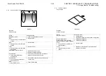
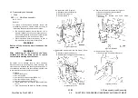
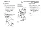
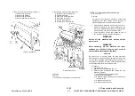
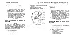
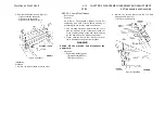
5. Remove the R/H Chute Assembly. (Figure-1)
1) Remove the screws (2).
2) Remove the screws (2).
3) Remove the R/H Chute Assembly.
(Figure-1)j0hn4203
Installation
Procedure
1. Perform the removal steps in reverse order.
Summary of Contents for WorkCentre Pro 423
Page 2: ......
Page 3: ...WorkCentre Pro 423 428 6HUYLFH 0DQXDO...
Page 6: ......
Page 8: ......
Page 9: ...INTRODUCTION...
Page 10: ......
Page 24: ...WorkCentre 423 428 03 02 INTRODUCTION 14 7 Translation of Warnings...
Page 25: ...CHAPTER 1 SERVICE CALL PROCEDURE...
Page 26: ......
Page 28: ...WorkCentre Pro 423 428 1 2 CHAPTER 1 SERVICE CALL PROCEDURE 03 02 1 1 Trimming...
Page 31: ...CHAPTER 2 TROUBLESHOOTING...
Page 32: ......
Page 76: ...WorkCentre Pro 423 428 2 44 CHAPTER 2 TROUBLESHOOTING 03 02 2 3 Level 2 Troubleshooting...
Page 243: ...CHAPTER 3 IMAGE QUALITY TROUBLESHOOTING...
Page 244: ......
Page 273: ...CHAPTER 4 DISASSEMBLY ASSEMBLY AND ADJUSTMENT...
Page 274: ......
Page 329: ...CHAPTER 5 PARTS LIST...
Page 330: ......
Page 415: ...03 02 5 2 Parts List WorkCentre Pro 423 428 5 85 CHAPTER 5 PARTS LIST...
Page 416: ...CHAPTER 6 GENERAL...
Page 417: ......
Page 456: ...CHAPTER 7 ELECTRICAL WIRING DIAGRAMS...
Page 457: ......
Page 476: ...CHAPTER 8 ACCESSORIES...
Page 477: ......
Page 535: ...WorkCentre Pro 423 428 8 58 CHAPTER 8 ACCESSORIES 03 02 8 22 Stamp Kit Red...
Page 536: ...CHAPTER 9 BSD Block Schematic Diagram...
Page 537: ......
Page 541: ......
Page 542: ......
Page 543: ......
Page 544: ......
Page 545: ......
Page 546: ......
Page 547: ......
Page 548: ......
Page 549: ......
Page 550: ......
Page 551: ......
Page 552: ......
Page 553: ......
Page 554: ......
Page 555: ......
Page 556: ......
Page 557: ......
Page 558: ......
Page 559: ......
Page 560: ......
Page 561: ......
Page 562: ......
Page 563: ......
Page 564: ......
Page 565: ......
Page 566: ......
Page 567: ......
Page 568: ......
Page 569: ......
Page 570: ......
Page 571: ......
Page 572: ......
Page 573: ......
Page 574: ......
Page 575: ......
Page 576: ......
Page 577: ......
Page 578: ......
Page 579: ......
Page 580: ......
Page 581: ......
Page 582: ......
Page 583: ......
Page 584: ......
Page 585: ......
Page 586: ......
Page 587: ......
Page 588: ......
Page 589: ......
Page 590: ......
Page 591: ......
Page 592: ......
Page 593: ......
Page 594: ......
Page 595: ......
Page 596: ......
Page 597: ......
Page 598: ......
Page 599: ......
Page 600: ......
Page 601: ......
Page 602: ......
Page 603: ......
Page 604: ......
Page 605: ......
Page 606: ......
Page 607: ......
Page 608: ......
Page 609: ......
Page 610: ......
Page 611: ......
Page 612: ......
Page 613: ......
Page 614: ......
Page 615: ......
Page 616: ......
Page 617: ......
Page 618: ......
Page 619: ......

