WorkCentre Pro 423/428
8-34
CHAPTER 8 ACCESSORIES
03/02
8.13 ISDN/G4 Kit
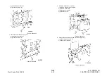
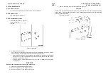
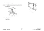
10. Remove the Screws (6) and the Option Box Cover.
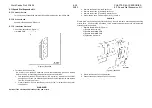
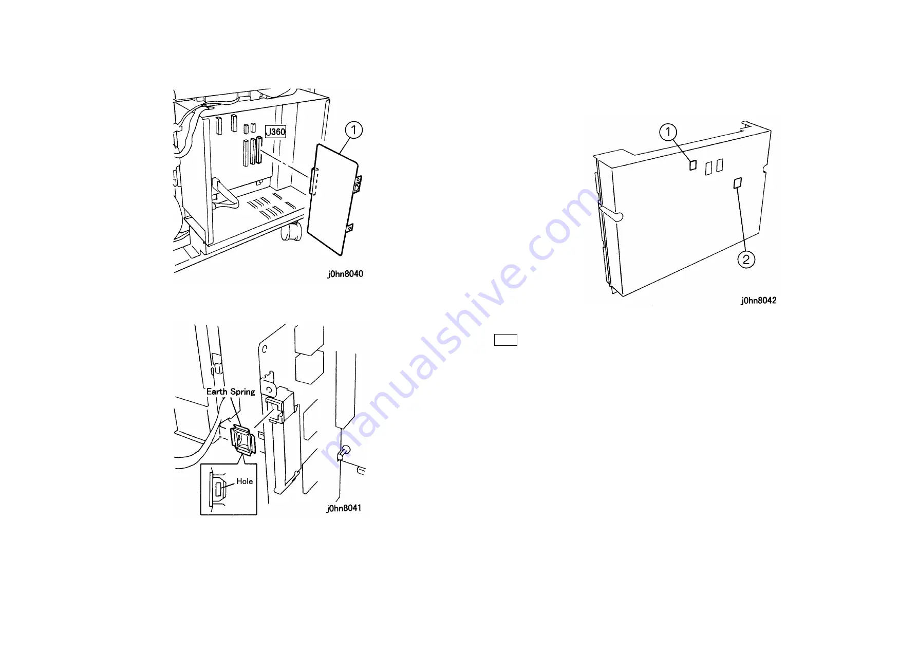
11. Install the G4/ICM PWB. (Figure-6)
1) Connect the G4/ICM PWB to J360.
(Figure-6) j0hn8040
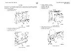
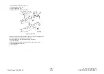
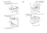
12. Place the Earth Spring gently with the holes (2) on the side. (Figure-7)
(Figure-7) j0hn8041
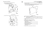
13. Return the Option Box Cover removed in Step 10 and secure the G4/ICM PWB using
the Screws (2) in the Kit.
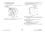
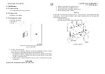
14. Provide an access hole in the Rear Cover of the Cabinet for a modular jack.(Figure-8)
1) Remove the blind plate of HANDSET. (Machine with handset only)
2) Remove the blind plate of ISDN/ISDN LINE.
(Figure-8) j0hn8042
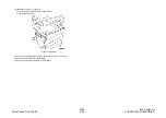
15. Return the machine to its original state.
Note
If the machine has a handset, change the handset modular jack connection from
the TEL terminal on the IOT Rear Cover to the HANDSET terminal on the
Cabinet Rear Cover.
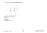
16. Connect the phone line to ISDN/ISDN LINE on the Cabinet Rear Cover with INS64
Cable.
17. Connect the power cord and turn on the power.
18. Check that the “G4” is displayed on the IIT display.
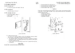
19. Check whether the G4M is installed.
1) Enter C/E Mode.
2) Set the Chain/Function code "50/107" and press the Start button.
3) Check that the set value is 1.
20. Check whether the ICM is installed.
1) Set the Chain/Function code "50/109" and press the Start button.
2) Check that the set value is 1.
3) Exit C/E Mode.
21. Set the [Local Fax Information] items 21 and 23 to 38.
Summary of Contents for WorkCentre Pro 423
Page 2: ......
Page 3: ...WorkCentre Pro 423 428 6HUYLFH 0DQXDO...
Page 6: ......
Page 8: ......
Page 9: ...INTRODUCTION...
Page 10: ......
Page 24: ...WorkCentre 423 428 03 02 INTRODUCTION 14 7 Translation of Warnings...
Page 25: ...CHAPTER 1 SERVICE CALL PROCEDURE...
Page 26: ......
Page 28: ...WorkCentre Pro 423 428 1 2 CHAPTER 1 SERVICE CALL PROCEDURE 03 02 1 1 Trimming...
Page 31: ...CHAPTER 2 TROUBLESHOOTING...
Page 32: ......
Page 76: ...WorkCentre Pro 423 428 2 44 CHAPTER 2 TROUBLESHOOTING 03 02 2 3 Level 2 Troubleshooting...
Page 243: ...CHAPTER 3 IMAGE QUALITY TROUBLESHOOTING...
Page 244: ......
Page 273: ...CHAPTER 4 DISASSEMBLY ASSEMBLY AND ADJUSTMENT...
Page 274: ......
Page 329: ...CHAPTER 5 PARTS LIST...
Page 330: ......
Page 415: ...03 02 5 2 Parts List WorkCentre Pro 423 428 5 85 CHAPTER 5 PARTS LIST...
Page 416: ...CHAPTER 6 GENERAL...
Page 417: ......
Page 456: ...CHAPTER 7 ELECTRICAL WIRING DIAGRAMS...
Page 457: ......
Page 476: ...CHAPTER 8 ACCESSORIES...
Page 477: ......
Page 535: ...WorkCentre Pro 423 428 8 58 CHAPTER 8 ACCESSORIES 03 02 8 22 Stamp Kit Red...
Page 536: ...CHAPTER 9 BSD Block Schematic Diagram...
Page 537: ......
Page 541: ......
Page 542: ......
Page 543: ......
Page 544: ......
Page 545: ......
Page 546: ......
Page 547: ......
Page 548: ......
Page 549: ......
Page 550: ......
Page 551: ......
Page 552: ......
Page 553: ......
Page 554: ......
Page 555: ......
Page 556: ......
Page 557: ......
Page 558: ......
Page 559: ......
Page 560: ......
Page 561: ......
Page 562: ......
Page 563: ......
Page 564: ......
Page 565: ......
Page 566: ......
Page 567: ......
Page 568: ......
Page 569: ......
Page 570: ......
Page 571: ......
Page 572: ......
Page 573: ......
Page 574: ......
Page 575: ......
Page 576: ......
Page 577: ......
Page 578: ......
Page 579: ......
Page 580: ......
Page 581: ......
Page 582: ......
Page 583: ......
Page 584: ......
Page 585: ......
Page 586: ......
Page 587: ......
Page 588: ......
Page 589: ......
Page 590: ......
Page 591: ......
Page 592: ......
Page 593: ......
Page 594: ......
Page 595: ......
Page 596: ......
Page 597: ......
Page 598: ......
Page 599: ......
Page 600: ......
Page 601: ......
Page 602: ......
Page 603: ......
Page 604: ......
Page 605: ......
Page 606: ......
Page 607: ......
Page 608: ......
Page 609: ......
Page 610: ......
Page 611: ......
Page 612: ......
Page 613: ......
Page 614: ......
Page 615: ......
Page 616: ......
Page 617: ......
Page 618: ......
Page 619: ......

