03/02
Overview
WorkCentre Pro 423/428
9-3
CHAPTER 9 BSD (Block Schematic Diagrams)
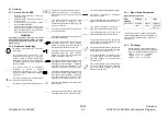
9.1 Overview
9.1.1 How to Use the BSD
1.
Enter the chain indicated in "Section 2
Troubleshooting."
2.
Another method of entering the chain is
to see Contents.
3.
In the chain you have entered, analyze
the test data and problem.
4.
Once the fault has been located, check
the parts list (PL) number or adjustment
(ADJ) number and go to the part indexes
or the specified ADJ section.
WARNING
Disconnect the power cord from the outlet
while performing any tasks that do not need
electricity. Contact with electricity can cause
death or injury..
9.1.2 Reference
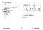
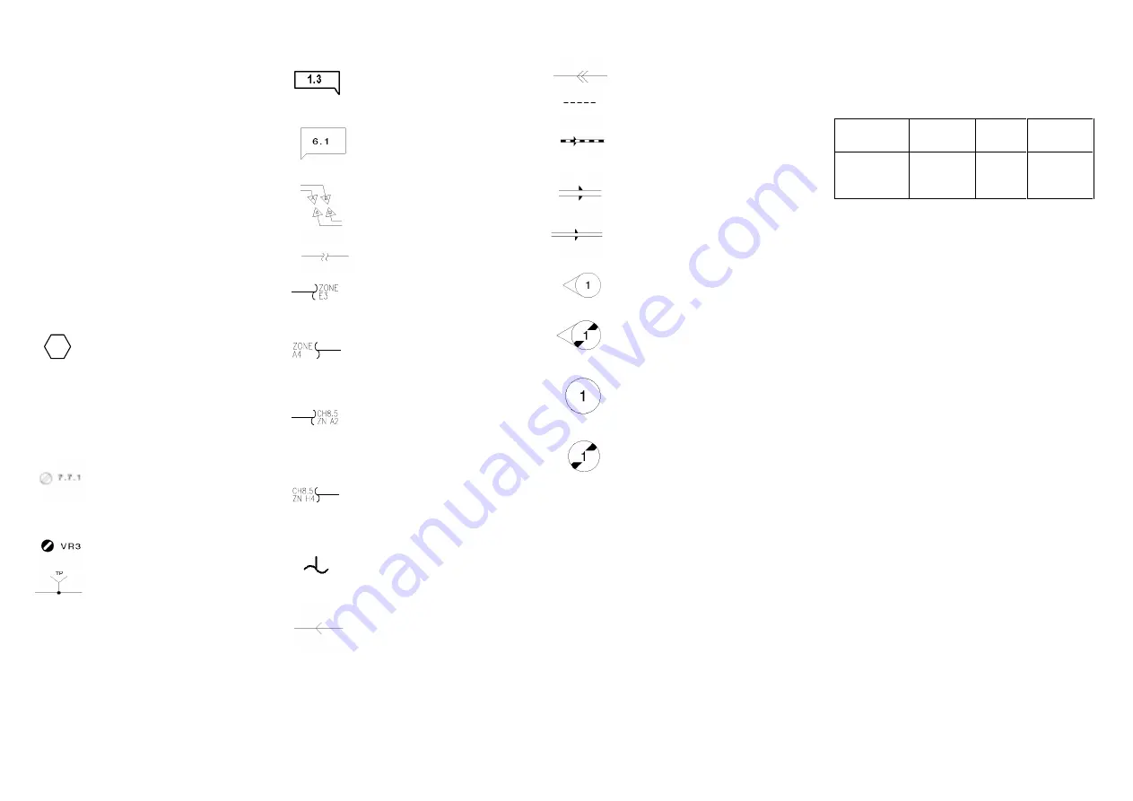
Symbology
This symbol usually refers to a note on the
same page.
This symbol refers to a parts list. "PL"
represents Parts List and "7.7" represents
a plate number to indicate that the part
information is given on the specified plate.
This symbol is added to every replaceable
part on the BSD.
This symbol refers to an adjustment
procedure in "Section 4 Repair/
Adjustment Procedures." "7.7.1" means
that the necessary adjustment procedure
is given in 7.7.1.
This symbol represents a variable resistor
that can be adjusted in field.
This symbol represents a signal test point.
This symbol indicates where the input to
the function comes from. "1.3" indicates
that the input comes from group function 3
of chain 1.
This symbol indicates where the output
from the function is going e.g. "6.1"
indicates that the output is going to group
function 1 of chain 6.
This symbol indicates that the signal line is
connected vertically.
This symbol indicates that the signal line is
connected horizontally.
This symbol indicates that the signal line is
connected within the same function.
"ZONE E3" means that the destination of
the signal line is indicated in zone E-3.
This symbol indicates that the signal line is
connected within the same function.
"ZONE A4" means that the source of the
signal is indicated in zone A-4.
This symbol indicates that the signal line is
connected to another sheet (written in the
lower right corner of the BSD). "CH8.5 ZN
A2" means that the destination of the
signal line is indicated in CH8.5 zone A-2.
This symbol indicates that the signal line is
connected to another sheet (written in the
lower right corner of the BSD). "CH8.5 ZN
H4" means that that the source of the
signal line is indicated in CH8.5 zone H-4.
This symbol represents the output power
line of Chain 1.
This symbol indicates that the signal flows
in the opposite direction, from left to right.
This symbol represents a feedback signal.
This symbol represents a mechanical
connection to a part.
This symbol identifies a mechanical drive
signal and indicates the signal direction.
This symbol identifies a document or
paper and indicates the signal direction.
This symbol identifies a heat, light, or air
signal and indicates the signal direction.
This symbol indicates that the part pointed
by this symbol has been changed by the
tag number within the circle.
This symbol indicates that the part pointed
by this symbol has not yet been changed
by the tag number within the circle.
This symbol indicates that the whole part
or only the framed part of the illustration
has been changed by the tag number
within the circle.
This symbol indicates that the whole part
or only the framed part of the illustration
has not yet been changed by the tag
number within the circle.
9.1.3 Signal Name Designation
Signal Name Composition
REGI
SENSOR
SENSED
(L)
+5VDC
Parts name
Operating
status
Logical
value
Voltage at
high signal
level (H)
This signal goes low (L) when the registration
sensor detects paper, and it goes high (H) (+5
VDC) when the registration sensor does not
detect paper.
9.1.4 DC Voltage
Measure the DC voltage between each
test point and the frame unless specified in
Note. DC voltage ranges are as follows:
+5VDC
+ 4.5
to
+ 5.3VDC
±
12VDC + 11.0 to +
12.6VDC
+24VDC + 22.0 to+ 25.7VDC
3/
1
Summary of Contents for WorkCentre Pro 423
Page 2: ......
Page 3: ...WorkCentre Pro 423 428 6HUYLFH 0DQXDO...
Page 6: ......
Page 8: ......
Page 9: ...INTRODUCTION...
Page 10: ......
Page 24: ...WorkCentre 423 428 03 02 INTRODUCTION 14 7 Translation of Warnings...
Page 25: ...CHAPTER 1 SERVICE CALL PROCEDURE...
Page 26: ......
Page 28: ...WorkCentre Pro 423 428 1 2 CHAPTER 1 SERVICE CALL PROCEDURE 03 02 1 1 Trimming...
Page 31: ...CHAPTER 2 TROUBLESHOOTING...
Page 32: ......
Page 76: ...WorkCentre Pro 423 428 2 44 CHAPTER 2 TROUBLESHOOTING 03 02 2 3 Level 2 Troubleshooting...
Page 243: ...CHAPTER 3 IMAGE QUALITY TROUBLESHOOTING...
Page 244: ......
Page 273: ...CHAPTER 4 DISASSEMBLY ASSEMBLY AND ADJUSTMENT...
Page 274: ......
Page 329: ...CHAPTER 5 PARTS LIST...
Page 330: ......
Page 415: ...03 02 5 2 Parts List WorkCentre Pro 423 428 5 85 CHAPTER 5 PARTS LIST...
Page 416: ...CHAPTER 6 GENERAL...
Page 417: ......
Page 456: ...CHAPTER 7 ELECTRICAL WIRING DIAGRAMS...
Page 457: ......
Page 476: ...CHAPTER 8 ACCESSORIES...
Page 477: ......
Page 535: ...WorkCentre Pro 423 428 8 58 CHAPTER 8 ACCESSORIES 03 02 8 22 Stamp Kit Red...
Page 536: ...CHAPTER 9 BSD Block Schematic Diagram...
Page 537: ......
Page 541: ......
Page 542: ......
Page 543: ......
Page 544: ......
Page 545: ......
Page 546: ......
Page 547: ......
Page 548: ......
Page 549: ......
Page 550: ......
Page 551: ......
Page 552: ......
Page 553: ......
Page 554: ......
Page 555: ......
Page 556: ......
Page 557: ......
Page 558: ......
Page 559: ......
Page 560: ......
Page 561: ......
Page 562: ......
Page 563: ......
Page 564: ......
Page 565: ......
Page 566: ......
Page 567: ......
Page 568: ......
Page 569: ......
Page 570: ......
Page 571: ......
Page 572: ......
Page 573: ......
Page 574: ......
Page 575: ......
Page 576: ......
Page 577: ......
Page 578: ......
Page 579: ......
Page 580: ......
Page 581: ......
Page 582: ......
Page 583: ......
Page 584: ......
Page 585: ......
Page 586: ......
Page 587: ......
Page 588: ......
Page 589: ......
Page 590: ......
Page 591: ......
Page 592: ......
Page 593: ......
Page 594: ......
Page 595: ......
Page 596: ......
Page 597: ......
Page 598: ......
Page 599: ......
Page 600: ......
Page 601: ......
Page 602: ......
Page 603: ......
Page 604: ......
Page 605: ......
Page 606: ......
Page 607: ......
Page 608: ......
Page 609: ......
Page 610: ......
Page 611: ......
Page 612: ......
Page 613: ......
Page 614: ......
Page 615: ......
Page 616: ......
Page 617: ......
Page 618: ......
Page 619: ......

