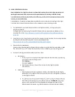
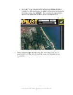
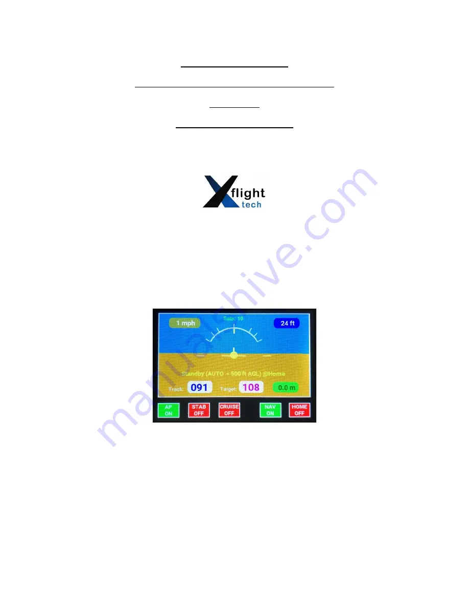
Xflighttech AUTOPILOT / TRIM, User'S Installation Manual
Get your Xflighttech AUTOPILOT / TRIM up and running smoothly with our comprehensive User's Installation Manual. This detailed manual is available for free download at 88.208.23.73:8080, providing step-by-step instructions and essential information to maximize the performance of your autopilot system.
Share
Download


Reviews:
No comments
Related manuals for AUTOPILOT / TRIM

PT500
Brand: YOKOGAWA Pages: 132

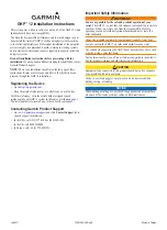
Reactor 40 Kicker
Brand: Garmin Pages: 28
GHC 10
Brand: Garmin Pages: 26

G-PILOT 3380
Brand: Navman Pages: 32
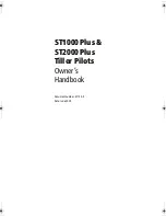
ST1000+
Brand: Raymarine Pages: 76
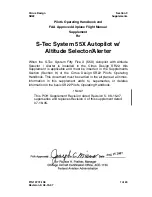
System 55X
Brand: S-TEC Pages: 24
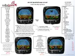
AV-30
Brand: uAvionix Pages: 4
GHP 20 Marine Autopilot System for...
Brand: Garmin Pages: 20
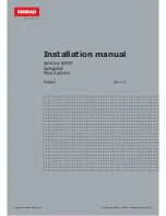
AP50
Brand: Simrad Pages: 142
GHP 12 Autopilot System
Brand: Garmin Pages: 32
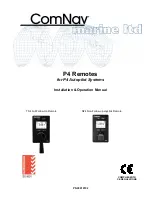
P4 Remotes Series
Brand: ComNav Pages: 40
Autohelm ST1000
Brand: AUTOHELM Pages: 35

SAS-70
Brand: Samyung ENC Pages: 33
AP56
Brand: TMQ Pages: 24

KFC225
Brand: BENDIXKing Pages: 25
Verado
Brand: Raymarine Pages: 72
Ace One
Brand: dji Pages: 44

SmartPilot X-5 ST6002 Controller
Brand: Raymarine Pages: 2


