
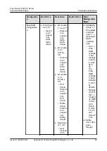
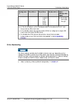


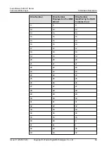
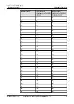
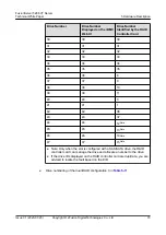

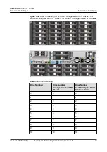
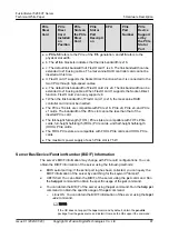
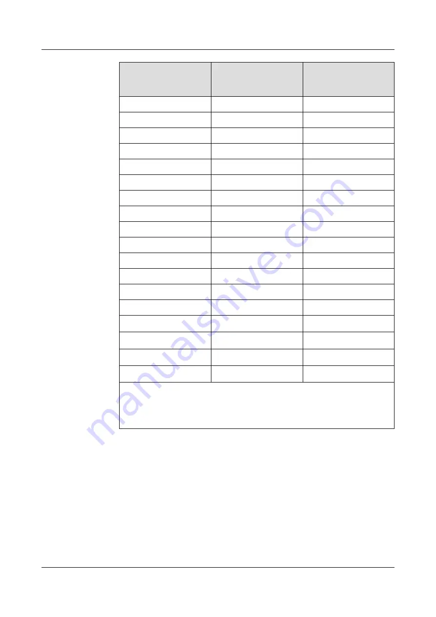
Drive Number
Drive Number
Displayed on the iBMC
WebUI
Drive Number
Identified by the RAID
Controller Card
30
30
30
31
31
31
32
32
32
33
33
33
34
34
34
35
35
35
36
36
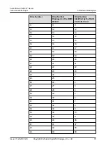
8
37
37
9
38
38
10
39
39
11
40
40
0
41
41
1
42
42
36
43
43
37
44
44
12
Note
45
45
13
Note
46
46
14
Note
47
47
15
Note
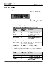
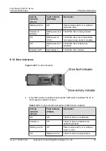
● Note: Only when the slot is configured with a SAS/SATA drive, the RAID
controller card can manage the drive and allocate a number to the drive.
● If the drive IDs displayed on the RAID controller card are duplicate, you are
advised to locate the fault based on the EID.
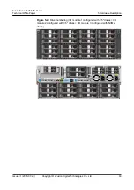
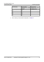
●
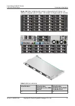
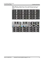
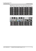
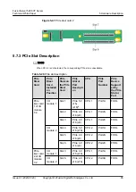
Drive numbering of the dual-RAID configuration 3 in
FusionServer 5288 V7 Server
Technical White Paper
5 Hardware Description
Issue 01 (2023-07-20)
Copyright © xFusion Digital Technologies Co., Ltd.
73


