background image


CN3200 Access Point - Installation Guide - G7604 - Release 3.3 

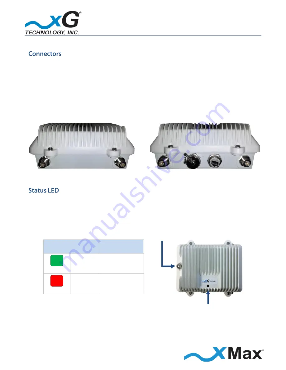
The CN3200 Modem features seven connectors: 


Four external xMax antenna connectors


(N-type / female) 


A connector for an external 2.4 GHz antenna (TNC-type / female) 


A weatherproof Ethernet connector 


An unused connector 


TOP CONNECTORS 


BOTTOM CONNECTORS 


Tx 3 


Tx 1 

  Tx/Rx 4  Unused Port 

Ethernet 

Tx/Rx 2 


The CN3200 Modem Status LED indicates power, network status, and hardware fault conditions. 
Under normal operating conditions, the LED glows 

GREEN


2.4 GHz ANTENNA CONNECTOR 


xMax Network 

GREEN 

SOLID 

CONNECTED 

RED 

SOLID 

NOT 

CONNECTED 


STATUS LED 


Summary of Contents for CN3200

Page 1: ...G7603 Release 3 3...

Page 2: ...x are registered trademarks of xG Technology Inc All other trademarks used herein are property of their respective owners For the latest product documentation and software updates please refer to our...

Page 3: ...to the WiFi Access Point 16 Antenna Considerations 17 Antenna Configuration 18 Installation Preparation 19 Assemble Your Parts and Tools 19 Equipment Provided in the Standard CN3200 Dual Band Routing...

Page 4: ...Dual Band Routing Modem to the xMax Network 34 Wired Internet Connectivity and Setting Up a WiFi Hotspot 35 Wired Internet Connectivity 35 Technical Specifications 36 Warranty 37 Limited Warranty 37 S...

Page 5: ...00 Access Point Installation Guide G7604 Release 3 3 List of Figures Figure 1 Antenna Configuration 18 Figure 2 CN3200 Dual Band Routing Modem Parts Checklist 19 Figure 3 Installation Tool Kit Checkli...

Page 6: ...6 CN3200 Access Point Installation Guide G7604 Release 3 3 THIS PAGE INTENTIONALLY LEFT BLANK...

Page 7: ...wireless devices to the xMax Network IMPORTANT The CN3200 Modem is shipped with the parts needed for basic installation and operation These items are shown below Be sure each of these items is include...

Page 8: ...d moisture The CN3200 Modem is a Power over Ethernet PoE device The IEEE 802 3at PoE standard enables transmission of both data and the power to operate a device over a single Cat5e cable connection T...

Page 9: ...enna TNC type female A weatherproof Ethernet connector An unused connector TOP CONNECTORS BOTTOM CONNECTORS Tx 3 Tx 1 Tx Rx 4 Unused Port Ethernet Tx Rx 2 The CN3200 Modem Status LED indicates power n...

Page 10: ...o the CN3200 Modem unit and ensure proper operation Lightning Protection MUST be used on all antenna connections and Ethernet tower runs Hazardous situation which if not avoided could result in death...

Page 11: ...cause harmful interference to radio communications However there is no guarantee that interference will not occur in a particular installation If this equipment does cause harmful interference to radi...

Page 12: ...7604 Release 3 3 Both top Tx RF ports MUST be properly terminated before power PoE is applied to the unit Applying power without proper RF port termination might damage the unit and void the product w...

Page 13: ...For more information see Wired Internet Connectivity and Setting Up a WiFi Hotspot on page 35 NOTES This procedure should be completed before installing the CN3200 Modem in a service location The setu...

Page 14: ...s takes approximately two minutes Before continuing wait until this process completes and the LED glows GREEN 1 On the computer open a Web browser 2 In the browser address line enter the IP address to...

Page 15: ...1 2 In the User name and Password fields enter User name webadmin Password NULL The password is case sensitive The first time the interface opens a warning displays that no password is set xG Technol...

Page 16: ...o button and then click Submit 7 On the Wireless Network Client page click the General Setup tab in the Device Configuration section select the required Transmit Power from the dropdown menu 8 Click t...

Page 17: ...PERFORMANCE The cables from the two Tx Rx connectors on the CN3200 Modem should be connected to the two antennas on one diagonal The cables from the two Rx connectors on the CN3200 Modem should be con...

Page 18: ...Antenna IMPORTANT Install the provided six 6 ferrite beads as shown by this marker in the wiring diagram xMax ANTENNA 2 4 GHz ANTENNA 110 240 VAC 50 60 Hz PoE Power Supply PoE Surge Protector ETHERNE...

Page 19: ...nology OBTAIN FROM YOUR PART SUPPLIER CN3200 Modem with Wall Mount Bracket UV resistant CMX outdoor rated Cat 5e UTP Ethernet Cables 4 6 mm OD lengths as required Weatherproof Ethernet Kit Data Cable...

Page 20: ...Kit Checklist 8 mm Metric Wrench 10 mm Metric Wrench 11 mm Metric Wrench Cat 5 Crimp Tool Digital Inclinometer or Magnetic Angle Locator Magnetic Compass or Smart Phone Compass App Colored Weatherpro...

Page 21: ...7604 Release 3 3 xMax Panel Antenna and Cables 2 4 GHz Panel Antenna with Mounting Bracket and Cable PoE Power Supply and AC Power Cord Weatherproof Ethernet Kit Ferrite Beads 6 Installation Bracket a...

Page 22: ...site Details regarding specific steps are found in dedicated topics as noted Optimum network performance can only be achieved through careful planning Most successful networks deploy multiple transmis...

Page 23: ...each end of each Ethernet cable run and then record the azimuth and tilt of each sector Refer to the example shown Antenna Sector Color Coding Tower Sector Degrees Azimuth Degrees Tilt Color 1 1 0 0 R...

Page 24: ...West 270 as shown on the compass rose Antenna Tilt Tilt of the antenna is the vertical angle of the antenna in relation to the horizon It is also referred to as elevation or inclination of the antenna...

Page 25: ...30 60 minutes Not including climb time Installation of Cat5 cabling 15 45 minutes Depending on length and difficulty Provisioning programming 15 minutes Installation of switch 15 30 minutes Installat...

Page 26: ...not exceed 100 m Proper materials used All equipment grounded All antenna azimuths correct and verified All antenna tilts correct and verified All hardware properly tightened Cable hangers in place Dr...

Page 27: ...sical compass is not available a free smart phone compass app can also be used After mounting again use the compass to ensure that the antenna azimuth is correct Do not fully tighten the mount until c...

Page 28: ...90 magnetic 6 Measure and adjust the tilt of the antenna to 0 with an inclinometer positioned against the back of the antenna Securely tighten all mounting bolts 7 Complete the remaining installation...

Page 29: ...ed mounting bracket and secure the CN3200 Modem to the bracket with four 4 hex head screws as shown Mounting Bracket 2 Align the bracket onto the threaded posts on the back of the xMax Panel Antenna a...

Page 30: ...4 U Bolts Locate the two supplied U bolts and then install them onto the mounting bracket as shown 5 2 4 GHz Panel Antenna Locate the supplied 2 4 GHz Panel Antenna and 24 inch cable The CN3200 Modem...

Page 31: ...ounting bracket lightly secure the CN3200 Modem xMax Panel Antenna assembly to the antenna mast 5 Orient the antenna towards the xMax Network station as described in the topic 6 Antenna Orientation Ov...

Page 32: ...ation where the CN3200 Modem and antennas are installed install a PoE Surge Protector at the location where the cable enters the building IMPORTANT The PoE Surge Protector MUST be properly grounded 14...

Page 33: ...and begins broadcasting beacons At this time the Status LED glows GREEN If backhaul is not available the Status LED glows RED 22 Test the operation of all transmission components using a Cat5 tester...

Page 34: ...power source Within 15 seconds after the power source is applied the Status LED glows RED If the CN3200 Modem is within range of an xMax Network it connects within 2 minutes and the LED glows GREEN Th...

Page 35: ...outing Modem for Internet access 1 Configure the device network interface for DHCP operation 2 Using an Ethernet cable connect the device to the CN3200 Dual Band Routing Modem The CN3200 Modem can be...

Page 36: ...p to 100 MPH Raw Data Rate Up to 6 Mbps RADIO PERFORMANCE Tx Power Output AVG RANGE 27 dBm in 1 dB steps Receiver Sensitivity 100 dBm BPSK 90 dBm QAM64 ANTENNA Four N type female connectors xMax one T...

Page 37: ...anty extends only to the original purchaser of the Product from xG or its authorized Resellers and is not assignable or transferable to any subsequent purchaser or end user xG s warranty applies only...

Page 38: ...the published specifications in effect when the software is first shipped by xG is to use commercially reasonable efforts to correct any reproducible material non conformity as determined by xG at it...

Page 39: ...damages direct indirect or consequential whether resulting from xG s negligence or otherwise arising out of in connection with or resulting from the goods sold to the Purchaser including without limit...

Page 40: ...G7603 Release 3 3 Copyright xG Technology Inc 2015 All Rights Reserved xG Technology Inc 240 South Pineapple Avenue Suite 701 Sarasota FL 34236 941 953 9035 www xGTechnology com...

Reviews: