background image

START menus: 

 
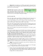
On this submenu you will find the parameters used 
during the engine startup. Like the “RUN” menus, 
some of these parameters could be not available in 
fadecs used in production engines. 
 

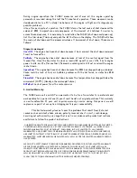
There are 3 start modes available:  
-

Manual

, where the user should do all the start 

sequence, and the fadec only control the pump and 
the fuel valve 
-

AUTO-Gas

: The fadec do all the start sequence automatically controlling the starter, 

glow plug, pump and valves, using auxiliary start gas (propane-butane) for ignition. 
-

AUTO-Kero

: The fadec do all the start sequence automatically controlling the starter, 

kerosene burner, pump and valves, using kerosene for ignition. This menu only appears in 
kerostart fadecs. 
 
Depending on the selected start mode the parameters available are only those related 
with the selected mode. 
 

Manual Start mode: 
 

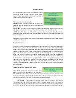
In order to start the engine in manual mode, the user must first raise the transmitter 
throttle trim and leave the throttle stick in idle/minimum position. The Light Emitting 
Diode (LED) on the FADEC illuminates, and the status screen show “Ready” indicating the 
system is "ready for start". Once in this position, the operator must 1) turn/spin up the 
engine with the starter motor / blower etc, 2) open the butane/propane gas, and ignite it.  
When the FADEC registers an exhaust temperature higher than the programmed 
start/minimum temperature and the rotor turning, the “Fuel Ramp” begins, the LED begins 
to blink and the system begins to pump fuel to the motor, raising the fuel pump power 
slowly until the idle speed is reached. This final condition is signaled by the system 
extinguishing the LED and the “Running” word on the status screen.  The user now has 
control of the engine power trough the throttle stick. Setting the trim to LOW the engine 
will be shutdown.


Parameters used in “manual start” mode: 
 

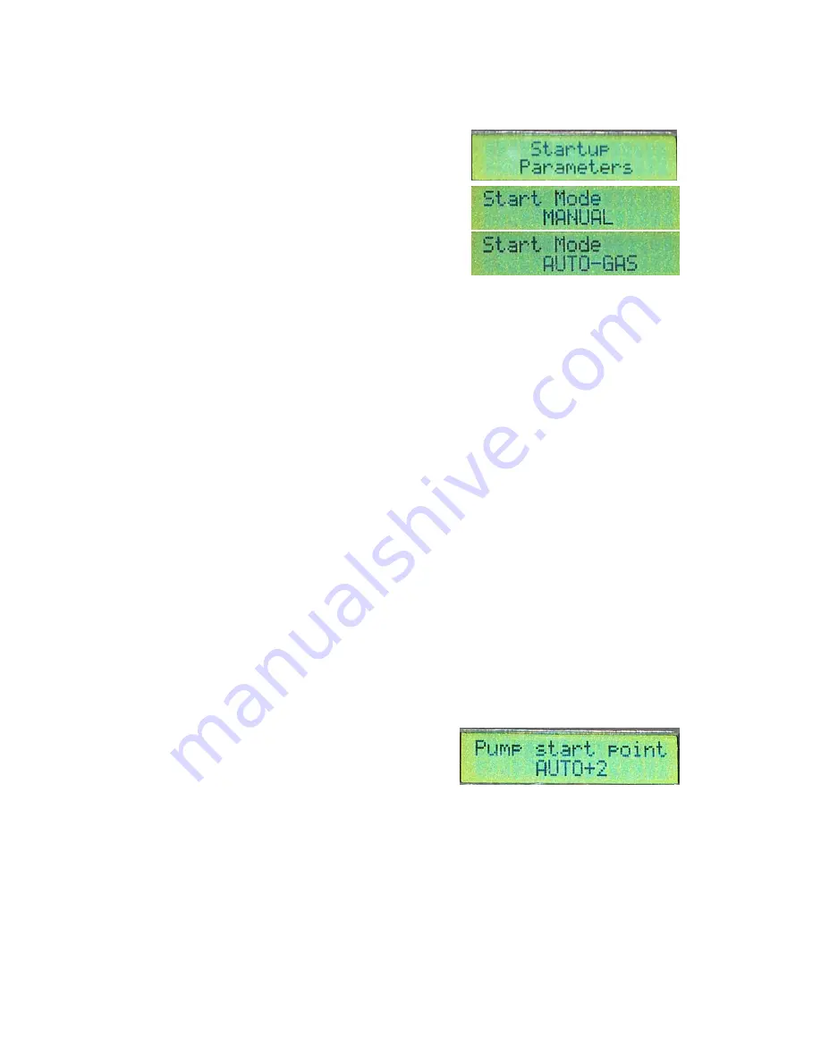
P

ump Start point

: Sets the power of the pump 

when it is started at beginning of the fuel ramp. 
The FADEC have the ability of to automatically adjust the pump power to start it at the 
lowest possible speed, independently of the battery voltage and pump roughness. Also the 
user has the possibility to adjust the minimum pump power manually. 


AUTO mode:  

The values of “Pump start point” from 0 to 8 are in AUTO mode. 

This means that the FADEC will adjust itself the pump power to start it slowly by 
measuring the voltage generated by the pump motor. The usual value for an unknown engine 
is AUTO+2, but after the first start you can increase or decrease the fuel flow if needed. 
 

Summary of Contents for FADEC system Autostart 10

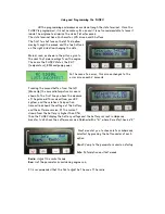
Page 1: ...0 Users Guide Torrent d en Puig 31 08358 Arenys de Munt Barcelona Spain E mail info xicoy com Fax 34 933 969 743 web www xicoy com Copyright 2010 Xicoy Electronica SL All Rights Reserved Manual conten...

Page 2: ...They should only be operated by those with the appropriate skills and knowledge to do so Incorrect operation or misuse can cause damage to property and bodily harm operators spectators and animals Xic...

Page 3: ...e FADEC are Temperature of the exhaust gas Battery voltage Barttery current Width of the throttle pulses from the radio transmitter Engine rotor RPM Engine run time External analog signal airspeed sen...

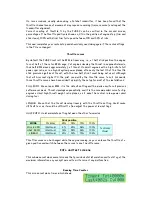
Page 4: ...ion to avoid short circuits specially in the starter connection it is very easy that the soldering in the red lead touch to the starter cover in some engines The male MPX plug provides the connection...

Page 5: ...s ready for a second servo signal but not used on present firmware Airspeed pitot sensor if used must be connected as shown in the picture at the side of the data terminal connection The last two sock...

Page 6: ...o the error screen each 2 seconds Pressing the second button from the left Menu Up the second informative screen is shown In the first line you have the measure of the pulse width received from your R...

Page 7: ...er button the setting WILL NOT be stored The screen will now change to Move the trim or switch the engine cut switch to on and throttle stick back to zero and again press the right hand button to stor...

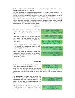
Page 8: ...gital TX the pilot can modify the throttle curve to suit his needs three throttle curves have been added to simplify the setup for most of the installations FULL EXPO Mean linear RPM it is the default...

Page 9: ...signal and this include the time that no pulses have been received On PCM and 2 4G systems the signal issued by the RX during a radio link failure depends of the programming of the failsafe settings...

Page 10: ...ns are only available when the Fadec is on Trim Low status that is to say recently powered up and receiving a STOP signal from the TX Pressing the button under the ON reading on the screen will energi...

Page 11: ...r values mean slower deceleration Stability delay When the engine is running at constant throttle setting the FADEC is adjusting continuously the pump power so that the rotor RPM mach exactly with the...

Page 12: ...must 1 turn spin up the engine with the starter motor blower etc 2 open the butane propane gas and ignite it When the FADEC registers an exhaust temperature higher than the programmed start minimum t...

Page 13: ...ontrol the flow rate of the start gas especially if pure propane is used Gas supplies must be gas only dip tube liquid feed types are not suitable Propane Butane mixtures work well in temperate climat...

Page 14: ...is being increased trough the time at the fuel ramp slope Once the rotor RPM arrive to the RPM set in rpm switch off gas parameter usually set at 3 4 of the starter off RPM the gas valve is closed and...

Page 15: ...starter during the preheat time The value usually is the same as Starter Power at Ignition but in some engines could be necessary to have higher power RPM 100 Starter The power applied to the starter...

Page 16: ...for tests Battery must be capable of to supply 20A Assure that the battery leads and igniter leads are of at lest 1mm2 cooper section Install the 2 solenoid valves at the pump output trough a t fittin...

Page 17: ...t the system wait for ignition Glow plug power Set the voltage of the burner 6 Once there is a confirmation of ignition the new phase is Preheat In this phase the burner continue with same electrical...

Page 18: ...ready for starting and that the transmitter signal corresponds to IDLE green LED lit StickLo This indicates that the throttle stick is in a position above IDLE the engine will not start with the stic...

Page 19: ...from the radio receiver 8 Limited Warranty The FADEC main unit and HDT are warranted to be free from defects in materials and workmanship for a period of one 1 year from the date of original purchase...

Page 20: ...The user must provide an emergency shut off i e a servo operated cut off valve for increased security Please read and follow the GTBA code of practice http www gtba co uk codes index htm...

Reviews: