7
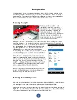
Measure using the laser:
Place the laser module close to the measuring tape, and move it until the line is
centered to the mark of the CG. Annotate the measure (72mm on the picture.
Measure using gravity:
Don’t worry if you don’t own the laser module, using the gravity the measure is easy to
do too. You just need three “high technology” components. Adhesive tape, sewing
thread and something heavy and pointed like an eyebolt.
Stick the sewing thread on the center of the CG mark using adhesive tape, and
annotate the measure (72mm on the picture).
Accuracy is similar in both cases, and more than enough for our application, but when
using the laser module, checks that it seats flat over the table, as if it is not absolutely
levelled, it can cause wrong readings. And when using the gravity, check that the
table is levelled. In both cases check that the sensor and the measuring tape are
correctly aligned to the reference used, that is the edge of the table in this example.
Now we know that the manufacturer recommends that the CG of our plane be located
at 72mm from the edge of the table. The CGMeter needs to know the distance from
the CENTER of the sensor to the recommended CG location. So we should remove the
25mm of offset, like we did previously. 72-25=47mm.
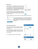
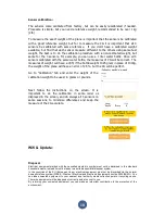
Click on “Data Entry” tab and enter the measured distance,
47mm in our example, to the “Distance Mains to CG” form.
Touch the “Submit” button to send this data to the CGMeter
and return to the measures screen.


