background image

XIEGU    COMMUNICATIONS 


3.1.4


Connection method between XPA125 and other QRP radio 

If you want to start the XPA125 power amplifier and put it into the transmit 
mode, you need to set the PTT port to a low level [level≤0.1V]. 
If the PTT output signal of the transceiver is at high level, the high level 
needs to be converted into a low level, and then input to the XPA125 
[ACC-PTT] port. 


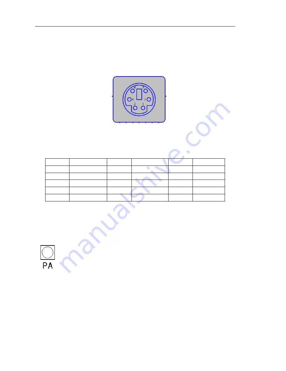
Pin 2 of the XPA125 ACC port is the PTT input port 


In order to achieve automatic band switching, the corresponding band voltage    
is needed. XPA125 band control voltage information is as follows. 


BAND 

LEVEL(mV) 

BAND 

LEVEL(mV) 

BAND 

LEVEL(mV) 

1.8 MHz 

230 

14.0 MHz 

1380 

50.0 MHz 

2530 

3.8 MHz 

460 

18.0 MHz 

1610 

---- 

---- 

5.0 MHz 

690 

21.0 MHz 

1840 

---- 

---- 

7.0 MHz 

920 

24.0 MHz 

2070 

---- 

---- 

10.0 MHz 

1150 

28.0 MHz 

2300 

---- 

---- 


3.2


Procedure: 

3.2.1


Using the  power  amplifier  unit  [PA  unit]  (ATU  unit  is  set  to BYPS) 


Press the PA key, so that the state of the amplifier is [INUSE].


If your connected transceiver is an X108G or X5105, please set 
the output power to 5 W. 

If you are using any other QRP transceiver, please set the output 
power to 1 W. 

Set  your  transceiver  to  CW  mode,  press  the  CW key to 
transmit, and the XPA125 amplifier will be activated. 

The output power of the XPA125 can be adjusted by adjusting 
the output power of the connected transceiver. 

Summary of Contents for XPA125

Page 1: ...XIEGU 100 W Solid State Linear Power Amplifier XPA125 Instruction Manual Copyright 2010 2017 Xiegu Communications...

Page 2: ...function Wide frequencyrangeof0 5 50 MHz Harmonic suppression of 39 dB Maximum output power can be automatically regulated via the ALC control when used with an X108G or X5105 transceiver Do not use...

Page 3: ...operating ambient temperature 55 Gain 13dB 2dB Supply voltage 12 14 5 V DC Current draw maximum output Standby 260 mA Transmit 30A 1 2 ATU Tuning frequency range 1 8 30 MHz 50 54 MHz Maximum tuning ra...

Page 4: ...for 2 seconds XPA125 will turn on ATU function key Via this button you can access the automatic antenna tuning function BAND selection key Using this button you can select between manual band switchin...

Page 5: ...otective plate 2 2 Rear panel layout 6 DC IN Power supply socket The XPA125 requires a 12 14 5 V DC supply 7 ANT Connector The ANT socket is connected to the antenna the connector model is SL16 K 8 FU...

Page 6: ...rface is for XPA125 firmware updates and connection to a PC 13 Handle 2 3 Display interface layout Input SWR value Displays the SWR value of the XPA125 input Operating voltage Displays the value of DC...

Page 7: ...ower input value to the XPA125 in Watts Current working band status Displays the current working band and whether automatic or manual mode is selected 9 Output power value Displays the output power be...

Page 8: ...cted to either socket Use suitable RF coaxial cable to connect the X108G ANT port to the XPA125 TRX port XPA125ANTportshould beconnected to theantenna 3 1 2 Method for connecting XPA125 with X5105 Use...

Page 9: ...d control voltage information is as follows BAND LEVEL mV BAND LEVEL mV BAND LEVEL mV 1 8 MHz 230 14 0 MHz 1380 50 0 MHz 2530 3 8 MHz 460 18 0 MHz 1610 5 0 MHz 690 21 0 MHz 1840 7 0 MHz 920 24 0 MHz 2...

Page 10: ...band Manual switching of frequency bands follows this order 160m 80m 60m 40m 30m 20m 17m 15m 12m 10m 6m 3 2 3 Using the automatic antenna tuner unit ATU PA unit is set to BYPS state Pressthe ATU butt...

Page 11: ...ndependently of each other You can therefore use the XPA125 as either an automatic antenna tuner or a separate power amplifier You can also bypass both units and your transceiver will then be connecte...

Page 12: ...ction function beyond a certain threshold The threshold of each sensor is as follows High SWR 3 0 High current 30A High voltage 15V DC Over temperature 100 Warning When the XPA125 current draw is too...

Page 13: ...r supply current Replace the power supply SWR is too high protection has been triggered Start ATU replace antenna coax Incorrect working mode Select the correct working mode Power amplifier unit not e...

Page 14: ...or the shipping both ways After two weeks XieGu will pay only for return shipping If the product is not covered under warranty the customer pays for shipping both ways plus the cost of the repair 2 Wa...

Page 15: ...ions are covered by the warranty A Damage caused by improper use by the user B Damage caused by an accident C Damage due to incorrect testing maintenance debugging or other changes D Damage is not cau...

Page 16: ...XIEGU COMMUNICATIONS 16 XIEGU COMMUNICATIONS www cqxiegu com...

Reviews: