7
the internal and external door frames is normal; is there any oil leakage at the hydraulic connection; is there any
abnormal wearing and tearing in the mechanical parts; is there any abnormal temperature rise or sparks in the
electric part, etc. If there is any abnormal situation, adjustment or trouble-shooting should be conducted promptly.
Level II maintenance:
Level II maintenance should be carried out as planned. Overall inspection should be
performed for the truck according to the following requirements.
a.
Maintenance for mechanical system:
Once half a year. The major content is to add lubricant to the
transmission gears and bearings of the drive wheel and the rotary joints, examine the firmness of the fixing fittings,
the flexibility of the wheels, as well as whether the forks can be lifted and lowered normally. The operation noise of
the truck shall not exceed 70 dB.
b. Maintenance for hydraulic system:
Once every 12 months. Examine if the oil cylinder is normal, if there is
any leakage externally or internally, if the hydraulic connection and the hose are reliable with no leakage. The
hydraulic oil should be kept clean and generally it should be replaced every 12 months. ISO oil product standard is
adopted for the hydraulic oil. When the ambient temperature is –5~ 40
℃
, HL-N46 or HL-N68 should be used; when
the ambient temperature is –35~ –5
℃
, HV-N46 or HV-N68 should be used. The replaced waste oil should be treated
according to the local rules and regulations.
c.
Maintenance for electric equipment:
Once every three months. First examine whether the specific gravity of
the electrolytic solution of the storage battery [specific gravity at 1.24 (at 25
℃
) in tropical areas and 1.26 (at 25
℃
)
in other areas] fits and the terminals are clean. Otherwise, the specific gravity of the electrolytic solution should be
adjusted as required and the terminals should be cleaned and painted with Vaseline and tightened. Then examine if
the connections of the electrical devices are reliable, the switches are normal and the insulation is ok (The insolating
resistance between the electrical devices and the truck body should be above 0.5M
Ω
).
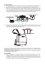
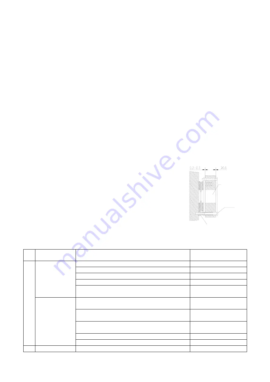
6.3 Adjustment of brake clearance
After a period of use, braking performance of the brake will decline due to the
wearing of the brake. Therefore, it is necessary to adjust the brake’s
clearance. As indicated in drawing on the right, check the clearance between
brake plate and magnetic steel with feeler, if the clearance is bigger than
0.5mm, clearance should be adjusted. Before adjustment, loosen the
tightening screws, adjust the length of the adjusting screws, and then screw
down the tightening screw. After the adjustment, the clearance between
brake plate and magnetic steel should be kept at 0.2-0.3mm. During the
adjustment, please pay attention to the balance adjustment of three lock
screws so as to ensure that clearance between brake plate and magnetic steel
is distributed evenly around.
7. Common faults and trouble shooting
No.
Trouble
Cause
Shooting
1
The stacker cannot
be started (The
contactor does not
work either.)
①
The fuse of the control circuit is burnt out.
Replace
②
The power switch contact is bad or damaged.
Repair or replace
③
The fuse of the major circuit is blown.
Replace
④
The contact of the electric lock switch is bad or damaged. Repair or replace
⑤
The connection of the storage batteries is loose or has
fallen off.
Tighten
The stacker cannot
be started (The
contactor works.)
①
The side-magnetic brake of the drive wheel does not suck
and the stacker is in a braked condition.
Repair or replace
②
The walking motor carbon brush is worn or bad contact
between the steering device and the carbon-brush.
Repair or replace
③
The magnet-exciting coil of the stepper motor is broken or
bad contact at the wire end.
Repair or replace
④
Bad contact
Repair or replace
⑤
There is a trouble at the MOSFET tube type circuit board. Repair or replace
2
The stacker can
①
Bad or broken contact.
Repair or replace
Steel magnet
Lock screw
Adjusting screw


