background image

AC701 Evaluation Board 

for the Artix-7 FPGA

User Guide

UG952 (v1.4) August 6, 2019

Summary of Contents for AC701

Page 1: ...AC701 Evaluation Board for the Artix 7 FPGA User Guide UG952 v1 4 August 6 2019...

Page 2: ...T AFFECT CONTROL OF A VEHICLE SAFETY APPLICATION UNLESS THERE IS A SAFETY CONCEPT OR REDUNDANCY FEATURE CONSISTENT WITH THE ISO 26262 AUTOMOTIVE SAFETY STANDARD SAFETY DESIGN CUSTOMER SHALL PRIOR TO U...

Page 3: ...1 Table 1 23 and Table 1 26 Updated Figure 1 42 Voltage regulators changed in section AC701 Board Power System page 67 Updated device types and footnotes in Table 1 27 to reflect device changes Update...

Page 4: ...AC701 Evaluation Board www xilinx com UG952 v1 4 August 6 2019...

Page 5: ...eneration 24 GTP Transceivers 35 PCI Express Edge Connector 38 SFP SFP Connector 39 10 100 1000 Mb s Tri Speed Ethernet PHY 41 Ethernet PHY User LEDs 43 USB to UART Bridge 43 HDMI Video Output 44 LCD...

Page 6: ...1 Board in a PC Chassis 89 Appendix E Board Specifications Dimensions 91 Environmental 91 Temperature 91 Humidity 91 Operating Voltage 91 Appendix F Regulatory and Compliance Information Overview 93 C...

Page 7: ...01 Board Features for a complete list of features The details for each feature are described in Feature Descriptions Additional Information See Appendix G Additional Resources for references to docume...

Page 8: ...ision clock multiplier Status LEDs Ethernet status Power good FPGA INIT FPGA DONE User I O User LEDs four GPIO User pushbuttons five directional CPU reset pushbutton User DIP switch 4 pole GPIO User S...

Page 9: ...wrist or ankle strap and ensure that it makes skin contact Connect the equipment end of the strap to an unpainted metal surface on the chassis Avoid touching the adapter against your clothing The wris...

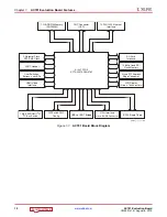
Page 10: ...Mb Quad SPI Flash Memory SD Card Interface 4 lane PCI Express Edge Connector LCD Display 2 line x 16 characters 1 KB EEPROM I2C I2C Bus Switch XADC Header User Switches Buttons and LEDs HDMI Video In...

Page 11: ...nces a component on the front side of the board 00 4 26 23 21 28 22 24 19 27 33 34 35 20 Table 1 1 AC701 Board Component Descriptions Callout Reference Designator Component Description Notes Schematic...

Page 12: ...tus LEDs green Lumex SML LX0603GW 15 21 DS2 DS5 User GPIO LEDs green Lumex SML LX0603GW 21 22 SW3 SW7 User pushbuttons E switch E Switch TL3301EF100QG 21 23 SW2 GPIO DIP switch 4 pole C K SDA04H1SBD 2...

Page 13: ...2 M1 and M0 are on SW1 positions 1 2 and 3 respectively as shown in Figure 1 3 The default mode setting is M 2 0 001 which selects Master SPI flash memory at board power on See Configuration Options f...

Page 14: ...charged from the VCC1V8 1 8V rail through a series diode with a typical forward voltage drop of 0 38V and 4 7 k current limit resistor The nominal charging voltage is 1 62V I O Voltage Rails In addit...

Page 15: ...nterface is implemented across I O banks 33 34 and 35 An external 0 75V reference VTTREF is provided for these banks Any interface connected to these banks that requires a reference voltage must use t...

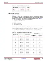
Page 16: ...STL15 18 DQ7 AF4 DDR3_D8 SSTL15 21 DQ8 AF5 DDR3_D9 SSTL15 23 DQ9 AF3 DDR3_D10 SSTL15 33 DQ10 AE3 DDR3_D11 SSTL15 35 DQ11 AD3 DDR3_D12 SSTL15 22 DQ12 AC3 DDR3_D13 SSTL15 24 DQ13 AB4 DDR3_D14 SSTL15 34...

Page 17: ...15 142 DQ39 C3 DDR3_D40 SSTL15 147 DQ40 D3 DDR3_D41 SSTL15 149 DQ41 A4 DDR3_D42 SSTL15 157 DQ42 B4 DDR3_D43 SSTL15 159 DQ43 C4 DDR3_D44 SSTL15 146 DQ44 D4 DDR3_D45 SSTL15 148 DQ45 D5 DDR3_D46 SSTL15 1...

Page 18: ...L15 10 DQS0_N V8 DDR3_DQS0_P SSTL15 12 DQS0_P AE5 DDR3_DQS1_N SSTL15 27 DQS1_N AD5 DDR3_DQS1_P SSTL15 29 DQS1_P AE1 DDR3_DQS2_N SSTL15 45 DQS2_N AD1 DDR3_DQS2_P SSTL15 47 DQS2_P V2 DDR3_DQS3_N SSTL15...

Page 19: ...ry Resources User Guide UG473 Ref 5 For more DDR3 SODIMM details see the Micron MT8JTF12864HZ 1G6G1 data sheet Ref 15 N8 DDR3_RESET_B LVCMOS15 30 RESET_B T3 DDR3_S0_B SSTL15 114 S0_B T2 DDR3_S1_B SSTL...

Page 20: ...connections of the Quad SPI flash memory on the AC701 board For more details see the Micron N25Q256A13ESF40G data sheet Ref 15 Table 1 5 Quad SPI Flash Memory Connections to the FPGA FPGA Pin U1 Schem...

Page 21: ...tions to FPGA U1 Figure 1 6 shows the J7 SPI flash memory external programming connector Table 1 6 SPI Flash Memory J7 Connections to the FPGA U1 FPGA Pin Schematic Net Name J7 Pin AE16 FPGA_PROG_B 1...

Page 22: ...7 Figure 1 7 SD Card Interface Table 1 7 SDIO Connections to the FPGA FPGA Pin U1 Schematic Net Name I O Standard U29 SDIO Connector Pin Number Pin Name R20 SDIO_SDWP LVCMOS33 11 SDWP P24 SDIO_SDDET L...

Page 23: ...priority over the configuration method selected through the FPGA mode pin settings at SW1 When an FMC card is attached to the AC701 board it is automatically added to the JTAG chain through electronic...

Page 24: ...lock sources available for the FPGA logic on the AC701 board see Table 1 8 X Ref Target Figure 1 9 Figure 1 9 JTAG Circuit UG952_c1_09_101512 JTAG_TDI FMC_TDI_BUF FPGA_TDO FPGA_TMS_BUF FPGA_TCK_BUF FP...

Page 25: ...re 1 10 Figure 1 10 AC701 Board Clocking Diagram UG952_c1_110_012015 U1 Artix 7 FPGA XC7A200T 2FBG676C Bank 16 Bank 15 Bank 14 Bank 13 Bank 12 Bank 36 Bank 35 Bank 34 Bank 33 Bank 32 GTP Quad 216 GTP...

Page 26: ...ser Clock Source Figure 1 2 callout 7 The AC701 board has a programmable low jitter 3 3V differential oscillator U34 driving the FPGA MRCC inputs of bank 14 This USER_CLOCK_P and USER_CLOCK_N clock si...

Page 27: ...ifferential clock circuit is shown in Figure 1 13 Note This user clock is input to FPGA bank 15 which is powered by VCCO_VADJ The VCCO_VADJ rail is typically 2 5V but can be reprogrammed to be either...

Page 28: ...C Connector HPC J30 ICS844021 125 Mhz Clock U2 X6 Crystal Oscillator 114 285 MHz 3 2 1 0 U3 0 1 2 3 U4 Rec_Clock_C_P N Pins D23 D24 SEP_MGT_CLK_SEL 1 0 Pins C24 B26 PCIE_MGT_CLK_SEL 1 0 Pins C26 A24 E...

Page 29: ...ock Inputs Clock Source Schematic Net Name SY89544UMG U3 Schematic Net Name 1 FPGA U1 Bank 213 Device Ref Pin Input SEL 1 0 2 Pin Output Pin Pin Name ICS84402I U2 7 EPHYCLK_Q0_P IN0 00 4 10 Q 11 QB SF...

Page 30: ...WRPAD VT0 IN0 IN1 NC NC NC NC NC NC VT1 IN1 IN2 VT2 IN2 IN3 VT3 IN3 SEL0 SEL1 1 2 3 S0 S1 U3 SY89544UMG 50 50 50 50 50 50 50 50 VCC2V5 VCC2V5 FMC1_HBC_GBTCLK0_M2C_C_N EPHYCLK_Q0_P EPHYCLK_Q0_N SI5324_...

Page 31: ...T Clock Inputs Clock Source Schematic Net Name SY89544UMG U4 Schematic Net Name 1 FPGA U1 Bank 213 Device Ref Pin Input SEL 1 0 Pin Output Pin Pin Name SMA J25 1 SMA_MGT_REFCLK_P IN0 00 4 10 Q 11 QB S...

Page 32: ...D VT0 IN0 IN1 NC NC NC NC NC NC VT1 IN1 IN2 VT2 IN2 IN3 VT3 IN3 SEL0 SEL1 1 2 3 S0 S1 U4 SY89544UMG 50 50 50 50 50 50 50 50 VCC2V5 VCC2V5 FMC1_HBC_GBTCLK1_M2C_C_N SMA_MGT_REFCLK_P SMA_MGT_REFCLK_N SI5...

Page 33: ...ase input frequency and using an internal VCO multiplies this by five to produce a 0 45 ps typical RMS phase jitter 125 MHz LVDS output The circuit for the 125 MHz clock is shown in Figure 1 17 X Ref...

Page 34: ...e Silicon Labs Si5324 data sheet for more information on this device Ref 21 The SI5324 U24 connections to FPGA U1 are shown in Table 1 10 X Ref Target Figure 1 18 Figure 1 18 Jitter Attenuated Clock U...

Page 35: ...BT Clocks Figure 1 2 callout 29 The FMC HPC connector J30 sources two MGT clocks FMC1_HPC_GBTCLK0_M2C_P N from FMC connector section D J30 D4 P J30 D5 N is wired to SY89544UMG U3 IN2 pins 27 P and 25...

Page 36: ...TPTXP0_213 SFP_TX_P P3 18 SFP Conn P3 AD10 MGTPTXN0_213 SFP_TX_N P3 19 SFP Conn P3 AC12 MGTPRXP0_213 SFP_RX_P P3 13 SFP Conn P3 AD12 MGTPRXN0_213 SFP_RX_N P3 12 SFP Conn P3 GTPE2_CHANNEL_ X0Y1 AE9 MGT...

Page 37: ...GTPTXN2_216 PCIE_TX1_N P1 A22 2 PCIe edge conn P1 B13 MGTPRXP2_216 PCIE_RX1_P P1 B19 PCIe edge conn P1 A13 MGTPRXN2_216 PCIE_RX1_N P1 B20 PCIe edge conn P1 GTPE2_CHANNEL_ X0Y7 D10 MGTPTXP3_216 PCIE_TX...

Page 38: ...e FPGA through the MGTREFCLK0 pins of Quad 216 PCIE_CLK_Q0_P is connected to FPGA U1 pin F11 and the _N net is connected to pin E11 The PCI Express clock circuit is shown in Figure 1 20 PCIe lane widt...

Page 39: ...SCL SDA TX_DISABLE TX_FAULT GND11 2 3 LOW BW TX 2 3 LOW BW RX 1 2 FULL BW RX SFP Enable 1 2 FULL BW TX SFP_RS1 SFP_VCCT 32 21 22 23 24 25 26 27 28 29 30 19 18 16 15 13 12 8 20 17 14 10 11 1 7 9 6 5 4...

Page 40: ...R23 SFP_LOS 1 8 LOS Notes 1 For SFP_TX_DISABLE and SFP_LOS the I O standard LVCMOS33 Table 1 14 SFP Module Control and Status SFP Control Status Signal Board Connection SFP_TX_FAULT Test point J22 Hig...

Page 41: ...in magnetics On power up or on reset the PHY is configured to operate in RGMII mode with PHY address 0b00111 using the settings shown in Table 1 15 These settings can be overwritten by commands passe...

Page 42: ...rd M88E1116R U12 Pin Pin Name T14 PHY_MDIO LVCMOS18 45 MDIO W18 PHY_MDC LVCMOS18 48 MDC U22 PHY_TX_CLK LVCMOS18 60 TX_CLK T15 PHY_TX_CTRL HSTL 63 TX_CTRL U16 PHY_TXD0 HSTL 58 TXD0 U15 PHY_TXD1 HSTL 59...

Page 43: ...e USB cable is supplied in the evaluation kit standard A plug to host computer mini B plug to AC701 board connector J17 The CP2103GM is powered by the USB 5V provided by the host PC when the USB cable...

Page 44: ...HSYNC Single ended input CLK Interrupt Out Pin to FPGA I2C SPDIF Table 1 17 USB J17 Mini B Receptacle Pin Assignments and Signal Definitions USB Receptacle Pins J17 Receptacle Pin Name Schematic Net...

Page 45: ...37 75 47 26 76 77 49 19 1 30 U48 ADV7511 HDMI_D18 VCC1V8 HDMI_HEAC_C_N HDMI_AVDD HDMI_PLVDD HDMI_PLVDD 2 1 X5R 25V 0 1UF C78 HDMI_CLK HDMI_HSYNC HDMI_VSYNC HDMI_INT 1 1 1 10W 2 43K R105 R106 2 43K 1 1...

Page 46: ...6 LVCMOS18 80 D16 V24 HDMI_R_D17 LVCMOS18 78 D17 U20 HDMI_R_D18 LVCMOS18 74 D18 W23 HDMI_R_D19 LVCMOS18 73 D19 W20 HDMI_R_D20 LVCMOS18 72 D20 U24 HDMI_R_D21 LVCMOS18 71 D21 Y20 HDMI_R_D22 LVCMOS18 70...

Page 47: ...2 line by 16 character display is provided on the AC701 board Figure 1 26 Table 1 20 ADV7511 Connections to HDMI Connector ADV7511 U48 Schematic Net Name HDMI Connector P2 Pin 36 HDMI_D0_P 7 35 HDMI_...

Page 48: ...LCD Interface Circuit UG952_c1_25_100312 LCD Contrast Potentiometer LCD_RW LCD_DB4 LCD_DB6 LCD_RS LCD_E NC NC LCD_DB5 LCD_DB7 9 8 7 6 5 4 3 2 10 1 12 14 11 13 LCD_VEE GND VCCB B1 B2 B3 B4 B6 B7 GND A3...

Page 49: ...ired target downstream device The AC701 board I2C bus topology is shown in Figure 1 29 User applications that communicate with devices on one of the downstream I2C buses must first set up a path to th...

Page 50: ...0b0011000 Si5324 clock 7 0b1101000 Table 1 23 AC701 Board LEDs Reference Designator Description Notes Schematic Page DS1 INIT dual color red green Avago HSMF C155 7 DS2 GPIO LED0 Lumex SML LX0603GW 2...

Page 51: ...SER_SMA_GPIO_N J33 J34 2 line x 16 character LCD character display callout 18 If the display is unmounted connector J23 pins are available as 7 independent GPIOs 6 pin in line male 0 1 inch PMOD heade...

Page 52: ...gure 1 30 Figure 1 30 User LEDs UG952_c1_28_100312 R147 49 9 1 DS2 R148 49 9 1 DS3 R149 49 9 1 DS4 R150 49 9 1 GND DS5 GPIO_LED_2 GPIO_LED_0 GPIO_LED_1 GPIO_LED_3 X Ref Target Figure 1 31 Figure 1 31...

Page 53: ...952_c1_140_011813 FPGA_1V5 CPU_RESET R41 4 7k 0 1 W 5 GND 4 3 2 1 SW8 X Ref Target Figure 1 33 Figure 1 33 GPIO DIP Switch UG952_c1_30_100412 SDA04H1SBD SW2 FPGA_1V5 GPIO_DIP_SW0 GPIO_DIP_SW1 GPIO_DIP...

Page 54: ...rget Figure 1 35 Figure 1 35 User SMA Connector USER_SMA_GPIO_P J34 USER_SMA_GPIO_N GND J33 GND UG952_c1_142_011813 SMA Connector SMA Connector X Ref Target Figure 1 36 Figure 1 36 LCD Header J23 UG95...

Page 55: ...SW4 3 T5 GPIO_SW_S SSTL15 SW5 3 R5 GPIO_SW_W SSTL15 SW7 3 U6 GPIO_SW_C SSTL15 SW6 3 User CPU_RESET Pushbutton Switch Active High U4 CPU_RESET SSTL15 SW8 3 User 4 Pole DIP Switch Active High R8 GPIO_D...

Page 56: ...rent pinout than J49 Connecting an ATX 6 pin connector into J49 damages the AC701 board and voids the board warranty Figure 1 38 shows the simplified diagram of the power connector J49 power switch SW...

Page 57: ...ard Quad SPI flash memory JTAG using a standard A to micro B USB cable for connecting the host PC to the AC701 board configuration port on the Digilent module Each configuration interface corresponds...

Page 58: ...d for signaling speeds up to 9 GHz 18 Gb s based on a 3 dB insertion loss point within a two level signaling environment Connector type Samtec SEAF series 1 27 mm 0 050 in pitch Mates with SEAM series...

Page 59: ..._P NA U4 27 A22 FMC1_HPC_DP1_C2M_P 1 AC8 B21 FMC1_HPC_GBTCLK1_M2C_N NA U4 25 A23 FMC1_HPC_DP1_C2M_N 1 AD8 B24 NC NA NA A26 NC NA NA B25 NC NA NA A27 NC NA NA B28 NC NA NA A30 NC NA NA B29 NC NA NA A31...

Page 60: ...E3 FMC1_HPC_HA01_CC_N LVCMOS25 AC21 F4 FMC1_HPC_HA00_CC_P LVCMOS25 AA19 E6 FMC1_HPC_HA05_P LVCMOS25 AD25 F5 FMC1_HPC_HA00_CC_N LVCMOS25 AB19 E7 FMC1_HPC_HA05_N LVCMOS25 AD26 F7 FMC1_HPC_HA04_P LVCMOS2...

Page 61: ...1 H16 FMC1_HPC_LA11_P LVCMOS25 B19 G19 FMC1_HPC_LA16_N LVCMOS25 D21 H17 FMC1_HPC_LA11_N LVCMOS25 A19 G21 FMC1_HPC_LA20_P LVCMOS25 M16 H19 FMC1_HPC_LA15_P LVCMOS25 B22 G22 FMC1_HPC_LA20_N LVCMOS25 M17...

Page 62: ...FMC1_HPC_HA11_N LVCMOS25 AE20 K13 FMC1_HPC_HA10_P LVCMOS25 AE22 J15 FMC1_HPC_HA14_P LVCMOS25 AE18 K14 FMC1_HPC_HA10_N LVCMOS25 AF22 J16 FMC1_HPC_HA14_N LVCMOS25 AF18 K16 FMC1_HPC_HA17_CC_P LVCMOS25 AA...

Page 63: ...TAVTT Switching Regulator 5 0V at 4A U46 Source Sink Regulator 0 75V at 3A U37 Source Sink Regulator 0 75V at 3A U36 Linear Regulator 1 7V 2 0V at 300 mA U10 Switching Module 1 5V at 6A U55 Switching...

Page 64: ...egulator VCC5V0 5 00V 34 TL1963ADCQR U62 1 5A 1 21V 5V adjustable LDO linear regulator VCC2V5 2 50V 48 TPS51200DR U37 3A source sink DDR termination regulator VTTDDR 0 75V 44 TPS51200DR U36 3A source...

Page 65: ...de switch SW15 is turned on and off Table 1 28 defines the voltage and current values for each power rail controlled by the UCD90120A U8 controller at PMBus Address 101 Table 1 29 defines the voltage...

Page 66: ...velop code to command the VCCO_VADJ rail to be set to 1 8V or 3 3V instead of the default setting of 2 5V See AC701 board schematic page 46 for a brief discussion concerning selectable VCCO_VADJ volta...

Page 67: ...set signals external interrupts cascading or other system functions 12 of these pins offer PWM functionality Using these pins the UCD90120A device offers support for margining and general purpose PWM...

Page 68: ...ammable input under voltage lockout output over voltage protection short circuits protection output current limit and allows start up into a pre biased output The sync input allows synchronization ove...

Page 69: ...V Nom Vin Vout EN FB Rail Enable PWM Margin Current Sense Voltage Sense 2 Low Pwr Select Rs 5m 12V V fb VCCINT 1 0V Cf Cf 1 GPIO Out FPWM Out ADC In ADC In Input Filter LMZ31506 U53 1 8V Nom Vin Vout...

Page 70: ...Power System Configuration Sequencer Schematic Regulator Type Voltage Current Page Page Contents Net Name 2 U9 PMBus Addr 102 5 rails 45 UCD90120A 2 46 Addr 102 Rail 1 VCCO_VADJ LMZ31506 U56 2 5V 6A...

Page 71: ...31503 U57 1 8V Nom Vin Vout EN FB Rail Enable PWM Margin Current Sense Voltage Sense 2 Rs 5m 12V V fb FPGA_1V8 1 8V Cf Cf VCC1V8 1 8V GPIO Out FPWM Out ADC In ADC In Input Filter LMZ31506 U58 3 3V Nom...

Page 72: ...20AADC input pin when the rail current is at its expected maximum current level as shown in Figure 1 44 U8 controller 1 and Figure 1 45 U9 controller 2 The UCD90120A has an assignable group of GPIO pi...

Page 73: ...PGA_1V8_XADC_CS_P N FPGA_3V3_XADC_P N FPGA_3V3_XADC_CS_P N MGTAVCC_XADC_P N MGTAVCC_XADC_CS_P N MGTAVTT_XADC_P N MGTAVTT_XADC_CS_P N NC ADG707BRU U14 S1A B S2A B S3A B S4A B S5A B S6A B S7A B S8A B DA...

Page 74: ...N 7 S5B V VCCO_VADJ NA VCCO_VADJ 2 5V remote sense divided to deliver 0 625V on FPGA_1V5_XADC_P VCCO_VADJ_XADC_P 24 S6A 101 VCCO_VADJ_SENSE_N 6 S6B I VCCO_VADJ CS 0A 3 2A U22 50 0V 0 796V VCCO_VADJ_XA...

Page 75: ...C_CS_P 25 S7A 110 MGTAVTT_XADC_CS_N 5 S7B Not used not connected Not connected 26 S8A 111 Not connected 4 S8B Table 1 34 XADC Measurements through Mux U13 Cont d Measurement Type Rail Name Current Ran...

Page 76: ...on 1 0V supply Jumper J42 can be used to select either an external differential voltage reference XADC_VREF or on chip voltage reference jumper J42 2 3 for the analog to digital converter X Ref Target...

Page 77: ...1 13 15 17 19 2 4 6 8 10 12 14 16 18 20 GND XADC_AGND XADC_AGND XADC_VCC5V0 VCCO_VADJ Table 1 35 XADC Header J19 Pinout Net Name J19 Pin Number Description XADC_VN _VP 1 2 Dedicated analog input chann...

Page 78: ...ser Guide UG480 Ref 10 for further details on configuration modes The method used to configure the FPGA is controlled by the mode pins M2 M1 M0 setting selected through DIP switch SW1 Table 1 36 lists...

Page 79: ...Figure 1 50 AC701 Board Quad SPI Flash Memory Configuration Circuit UG952_c1_42_072513 DQ 1 0 DQ2_WP DQ3_HOLD_B C S B U7 N25Q256A13ESF40G QUAD SPI TCK TMS TDI TDO Bank 0 CCLK VCCBATT M 2 0 DONE PROGR...

Page 80: ...80 www xilinx com AC701 Evaluation Board UG952 v1 4 August 6 2019 Chapter 1 AC701 Evaluation Board Features Send Feedback...

Page 81: ...r location of SW2 Default settings are shown in Figure A 1 and details are listed in Table A 1 X Ref Target Figure A 1 Figure A 1 SW2 Default Settings Table A 1 SW2 Default Switch Settings Position Fu...

Page 82: ...shown in Figure A 2 and details are listed in Table A 2 The default mode setting M 2 0 001 selects Master SPI flash memory configuration at board power on X Ref Target Figure A 2 Figure A 2 SW1 Defaul...

Page 83: ...3 SFP TX enabled 20 4 J8 1 2 VCCO_VADJ FMC voltage ON 45 5 J9 1 2 U35 REF3012 XADC_AGND L3 bypassed 29 6 J10 1 2 U35 REF3012 XADC_AGND GND 29 7 J11 1 2 XADC VCCINT 4A range 34 8 J52 None J52 1 INIT_B...

Page 84: ...Appendix A Default Switch and Jumper Settings 84 www xilinx com AC701 Evaluation Board UG952 v1 4 August 6 2019 X Ref Target Figure A 3 Figure A 3 AC701 Board Components Rev 2 0 8 BD B Send Feedback...

Page 85: ...DP5_M2C_N GND GND DP1_C2M_P DP1_C2M_N GND GND DP2_C2M_P DP2_C2M_N GND GND DP3_C2M_P DP3_C2M_N GND GND DP4_C2M_P DP4_C2M_N GND GND DP5_C2M_P DP5_C2M_N GND RES1 GND GND DP9_M2C_P DP9_M2C_N GND GND DP8_M...

Page 86: ...Appendix B VITA 57 1 FMC Connector Pinouts 86 www xilinx com AC701 Evaluation Board UG952 v1 4 August 6 2019 Send Feedback...

Page 87: ...priate pins and replace the net names in this list with net names in the user RTL For more information see Vivado Design Suite User Guide Using Constraints UG903 Ref 12 The FMC HPC connector J30 is co...

Page 88: ...Appendix C Xilinx Design Constraints 88 www xilinx com AC701 Evaluation Board UG952 v1 4 August 6 2019 Send Feedback...

Page 89: ...computer and remove the power cord from the PC 3 Open the PC chassis following the instructions provided with the PC 4 Select a vacant PCIe expansion slot and remove the expansion cover at the back o...

Page 90: ...Appendix D Board Setup 90 www xilinx com AC701 Evaluation Board UG952 v1 4 August 6 2019 8 Slide the AC701 board power switch SW15 to the ON position The PC can now be powered on Send Feedback...

Page 91: ...ns Dimensions Height 5 5 in 14 0 cm Length 10 5 in 26 7 cm Note The AC701 board height exceeds the standard 4 376 in 11 15 cm height of a PCI Express card Environmental Temperature Operating 0 C to 45...

Page 92: ...Appendix E Board Specifications 92 www xilinx com AC701 Evaluation Board UG952 v1 4 August 6 2019 Send Feedback...

Page 93: ...re maintained by the European Committee for Electrotechnical Standardization CENELEC IEC standards are maintained by the International Electrotechnical Commission IEC Electromagnetic Compatibility EN...

Page 94: ...those countries to which Xilinx is an importer Xilinx has also elected to join WEEE Compliance Schemes in some countries to help manage customer returns at end of life If you have purchased Xilinx br...

Page 95: ...n Kit Master Answer Record 51900 These Xilinx documents provide supplemental material useful with this guide 1 LogiCORE IP Tri Mode Ethernet MAC User Guide UG138 2 7 Series FPGAs Overview DS180 3 Arti...

Page 96: ...m UCD90120A TPS84621RUQ TPS84320RUQ LMZ31710 LMZ31704 TL1963ADC ADP123 TPS51200DR TPS79433DCQ TLV111733CDCY PCA9548 Documentation describing PMBus programming for the UCD90120A controller www ti com f...

Reviews: