Appendix A:
Default Switch and Jumper Settings
82
AC701 Evaluation Board
UG952 (v1.4) August 6, 2019
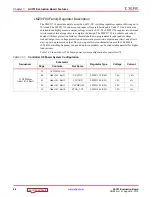
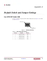
Configuration DIP Switch SW1
callout 28 for location of SW1. Default settings are shown in
and details
are listed in
.
The default mode setting M[2:0] =
001
selects Master SPI flash memory configuration at board
power-on.
X-Ref Target - Figure A-2
Figure A-2:
SW1 Default Settings
Table A-2:
SW1 Default Switch Settings
Position
Function
Default
1
FPGA_M2
M2
OFF
2
FPGA_M1
M1
OFF
3
FPGA_M0
M0
ON
UG952_aA_02_011813
SW1
OFF Position = 0
ON Position = 1
1
23
M2
M1
M0
ON

