background image

12 

Alveo Programming Cable User Guide 
UG1377 (v2019.

1

) September 17, 2019 

Chapter 4: Programming the Alveo Card 

If you are using the SDAccel

 flow, the 

Alveo U50 Data Center Accelerator Card Installation Guide


(

UG1370

provides the software installation instructions including programming the shell to the Alveo


card. Traditional RTL-flow Alveo cards, enabled with the 2x15-maintenance port, can be programmed 
using the Alveo Programming Module and the Vivado® hardware manager application.   
To use this flow: 

Vivado hardware manager must be installed on your host machine or laptop.

Alveo card must be installed (see 

Connecting Alveo Programming Module to Card

)


and the

server  powered on.

DMC connected as described i

Connecting Alveo Programming Module to Card

.

To connect and program the Alveo card using the Vivado hardware manager: 
1. Attach the free end of the USB cable (coming from the Alveo Programming Module) to the host

computer; thus connecting the module and host computer.

2. Start Vivado on the host computer
3. Open the hardware manager by selecting 

Flow Navigator > Open Hardware Manager

.

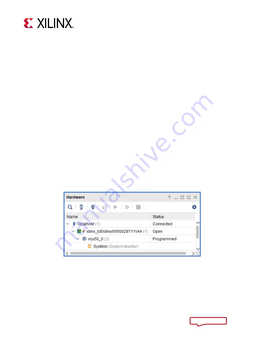
4. Select 

Tools > Auto Connect

 to open the target.

This will open a similar window as shown below.  In this example, an Alveo U50 is connected.

Figure 8: Vivado Hardware Manager Auto-Connect 

Send Feedback

Summary of Contents for Alveo U50

Page 1: ...Alveo Programming Cable User Guide UG1377 v2019 1 September 17 2019...

Page 2: ...rovided names of the supported cards and links to each Chapter 2 Preventing ESD Damage Updated Figure 1 Updated Tables 1 4 Chapter 3 Setting Up the System Updated Figures 2 7 Revised steps to set up r...

Page 3: ...Component Descriptions 6 Chapter 3 Setting Up the System with the Programming Cable 8 Connecting the Ribbon Cable 8 Disconnecting the Ribbon Cable 10 Connecting Alveo Programming Module to Card 10 Cha...

Page 4: ...Alveo programming cable consists of a programming module ribbon cable and USB cable Debug port enabled Alveo cards have a 2x15 pin connector which connects to the programming module via the ribbon cab...

Page 5: ...nd Alveo card Used for programming the FPGA 2 Micro USB Connector Port 1 Provides connection between host system with Vivado installed and the programming module Used for programming the Alveo card 3...

Page 6: ...ions Debug Header for Main Board Interconnection The programming module is populated with a 2x15 pin debug connector Callout 1 in Figure 1 which connects to the Alveo card via a ribbon cable 2x15 Conn...

Page 7: ...Description MANF MANF_P N Remarks 1 1 Ribbon Cables IDC Cables 050 Tiger Eye IDC Ribbon Cable Assembly 1 27 mm 30 Position 6 length Female to Female Samtec FFSD 15 D 06 00 01 N Connection between pro...

Page 8: ...ey IMPORTANT The ribbon length you use can vary depending on your system setup For ribbon cable length greater than 5 it is necessary to reduce the JTAG transfer frequency used by Vivado hardware mana...

Page 9: ...apply gentle pressure and ensure the cable has a tight connection IMPORTANT Do not apply excessive force when connecting the ribbon cable as the connector pins can be damaged or bent CAUTION When inst...

Page 10: ...er for ribbon cable access 1 Before installing the Alveo card connect one end of the ribbon cable to the 2x15 pin maintenance port on the Alveo card following the instructions outlined in Connecting t...

Page 11: ...Alveo Programming Module An image of both the ribbon on the left side and USB connected on the right side is shown below Figure 7 Alveo Programming Module with Ribbon and USB Cables Connected 7 Guide...

Page 12: ...on your host machine or laptop Alveo card must be installed see Connecting Alveo Programming Module to Card and the server powered on DMC connected as described in Connecting Alveo Programming Module...

Page 13: ...e manager command line as shown in the below image set_property PARAM FREQUENCY 1000000 current_hw_target Figure 9 Changing JTAG Transfer Frequency via TCL Command 5 Choose the memory configuration pa...

Page 14: ...7 In the Address Range drop down list select Entire Configuration Memory Device 8 Click OK Figure 11 Program Configuration Memory 9 Disconnect the card in the Vivado hardware manager 10 Disconnect the...

Page 15: ...endix A Board Specifications Dimensions Square Form Factor Height 2 5 inch 6 35 cm Length 2 5 inch 6 35 cm Thickness 5 0 062 inch 0 1574 cm Environmental Temperature for U200 and U280 Operating 0 C to...

Page 16: ...rior written consent Certain products are subject to the terms and conditions of Xilinx s limited warranty please refer to Xilinx s Terms of Sale which can be viewed at https www xilinx com legal htm...

Reviews: