5
Alveo Programming Cable User Guide
UG1377 (v2019.
1
) September 17, 2019
Chapter 2: Board Overview
The
Alveo™
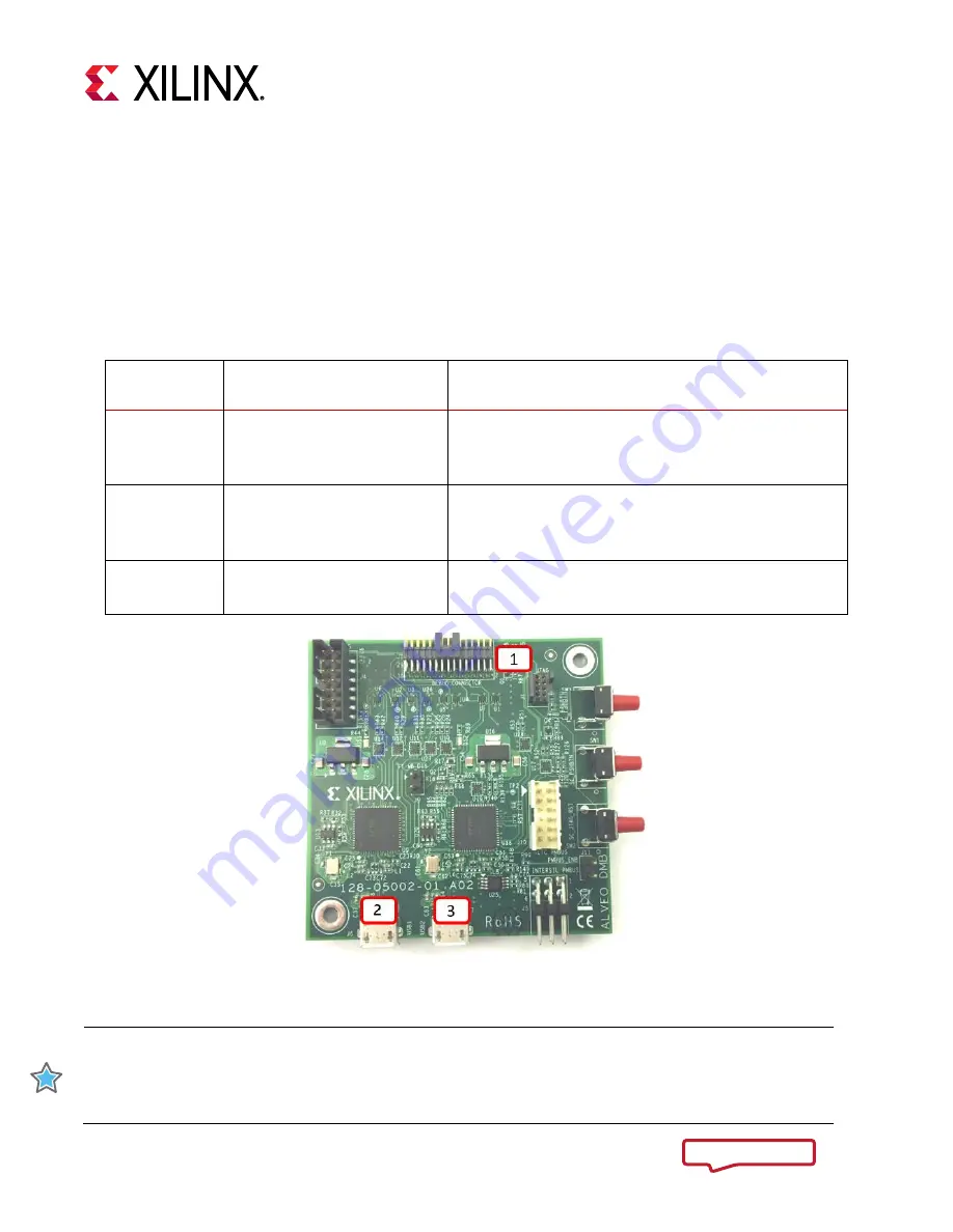
programming module, along with a callout of the available interfaces, is shown in the
following figure. The description of each call-out is given in the table below with additional information
provided in
in
Table 1: Alveo Programming Module Interface Descriptions
Call-Out No. Interface
Description
1
2x15-pin debug connector
Provides connection between the programming
module and Alveo card. Used for programming the
FPGA.
2
Micro USB Connector Port 1
Provides connection between host system, with Vivado
installed, and the programming module. Used for
programming the Alveo card.
3
Unused
Used exclusively by Xilinx for manufacturing.
Unused for development tool flows.
Figure 1: Alveo Programming Module Interface Locations
IMPORTANT:
While there are additional interfaces on the board, these will not be accessible on the
housed version of the DMC. Figure 1
is for visual reference only and might not reflect the current
revision of the board. There could be multiple revisions of this board. The specific details
concerning the differences between revisions are not captured in this document.


