background image

PCI Express Control Plane TRD

www.xilinx.com

23

UG918 (v2017.2) July 18, 2017

Chapter 3:

Bringing Up the Design

Run the Design on a Windows 7 Host Computer

After booting the Windows OS, follow these steps:

1. Repeat the steps in section 

Disable Driver Signature Enforcement, page 9

.

2. Open Device Manager (click 

Start > devmgmt.msc 

then press

 Enter

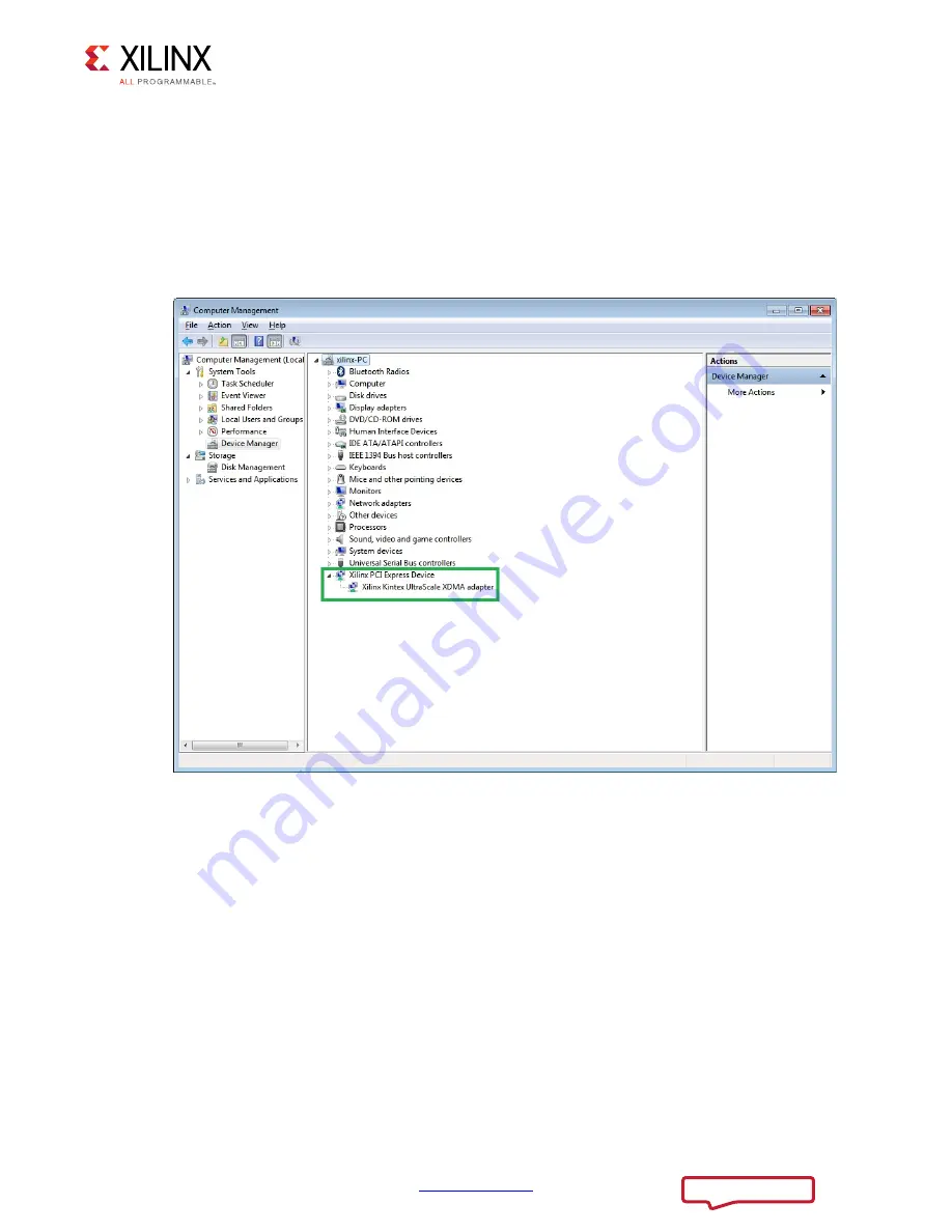
) and look for the 

Xilinx PCI Express Device as shown in 

Figure 3-9

.

X-Ref Target - Figure 3-9

Figure 3-9:

Xilinx PCI Express Device in Device Manager

UG918_c3_11_040715

Send Feedback

Summary of Contents for KCU105

Page 1: ...KCU105 PCI Express Control Plane TRD User Guide KUCon TRD01 Vivado Design Suite UG918 v2017 2 July 18 2017 ...

Page 2: ...leased with Vivado Design Suite 2015 4 with no changes from previous version 10 05 2015 2015 3 Released with Vivado Design Suite 2015 3 with minor textual edits 06 30 2015 2015 2 Released with Vivado Design Suite 2015 2 with no changes from previous version 05 05 2015 2015 1 Updated for Vivado Design Suite 2015 1 TRD ZIP file changed to rdf0305 kcu105 trd01 2015 1 zip Updated Information about res...

Page 3: ...from the LiveDVD Linux 14 Configure the FPGA 15 Run the Design on the Host Computer 21 Test the Reference Design 26 Remove Drivers from the Host Computer Windows Only 27 Chapter 4 Implementing and Simulating the Design Implementing the Base Design 28 Implementing the User Extension Design 31 Simulating the Base Design Using Vivado Simulator 32 Chapter 5 Targeted Reference Design Details and Modifi...

Page 4: ... Directory Structure Appendix B Recommended Practices and Troubleshooting in Windows Recommended Practices 45 Troubleshooting 45 Appendix C Additional Resources and Legal Notices Xilinx Resources 46 Solution Centers 46 References 46 Please Read Important Legal Notices 47 Send Feedback ...

Page 5: ...ates a control plane application using a PCI Express Endpoint block in a x1 Gen1 configuration Simple base address register BAR mapped read and write transactions are demonstrated using a kernel mode software driver controlled by the Control Monitoring graphical user interface GUI The top level block diagram of the TRD is shown in Figure 1 1 X Ref Target Figure 1 1 Figure 1 1 KCU105 PCI Express Co...

Page 6: ... capability AXI3 interface 64 bit kernel space drivers for Linux and Windows 7 which run on the host computer Control and monitoring graphical user interface GUI Resource Utilization Table 1 1 and Table 1 2 list the resources used by the base and user extension designs after synthesis Place and route can alter these numbers based on placements and routing paths These numbers are to be used as a ro...

Page 7: ...rce Utilization Resource Type Available Used Usage CLB Registers 484 800 44 395 9 16 CLB LUTs 242 400 27 817 11 48 Block RAM 600 24 4 MMCME3_ADV 10 1 10 Global Clock Buffers 240 3 1 25 BUFG_GT 120 5 4 17 SYSMONE1 1 1 100 IOB 520 16 3 08 GTHE3_CHANNEL 20 1 5 GTHE3_COMMON 5 0 0 Table 1 1 Base Design Resource Utilization Cont d Resource Type Available Used Usage Send Feedback ...

Page 8: ...puter is required to run the Vivado Design Suite and confige the on board FPGA It can be a laptop or desktop computer with any operating system supported by Vivado tools such as Redhat Linux or Microsoft Windows 7 The reference design test configuration requires a host computer comprised of the chassis containing a motherboard with a PCI Express slot monitor keyboard and mouse A DVD drive is also ...

Page 9: ..._control_plane The TRD directory structure is described in Appendix A Directory Structure Install TRD Drivers on the Host Computer Windows 7 Note This section provides steps to install KUCon TRD drivers and is only applicable to a host computer running Windows 7 64 bit OS If running Linux proceed to Set DIP Switches page 11 This section includes steps to set up and install KUCon TRD drivers in a h...

Page 10: ...PCI Express Control Plane TRD www xilinx com 10 UG918 v2017 2 July 18 2017 Chapter 2 Setup X Ref Target Figure 2 1 Figure 2 1 Disable Driver Signature Enforcement UG918_c2_01_040315 Send Feedback ...

Page 11: ...nstallation 5 A warning screen displays as the drivers are installed because the drivers are not signed by a trusted certificate authority yet To install the drivers ignore the warning message and click Install this driver software anyway This warning message pops up two times Repeat this step 6 After installation is complete click Finish to exit the InstallShield Wizard Set DIP Switches Ensure th...

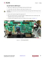
Page 12: ...TION Remove the power cord to prevent electrical shock or damage to the KCU105 board or other components 3 Ensure that the host computer is powered off 4 Open the chassis Select a vacant PCIe Gen3 capable expansion slot and remove the expansion cover at the back of the chassis 5 Plug the KCU105 board into the PCIe connector slot as shown in Figure 2 3 X Ref Target Figure 2 3 Figure 2 3 PCIe Connec...

Page 13: ...r supply adapter cable as shown in Figure 2 4 Note A 100 VAC 240 VAC input 12 VDC 5 0A output external power supply can be substituted for the ATX power supply 7 Slide the KCU105 board power switch SW1 to the ON position ON OFF is marked on the board X Ref Target Figure 2 4 Figure 2 4 Power Supply Connection to the KCU105 Board UG918_c3_02_040715 Send Feedback ...

Page 14: ...o host computers running Linux If running Windows 7 proceed to Configure the FPGA 1 Power on the host system and stop it in BIOS to select options to boot from the DVD drive BIOS options are entered by pressing DEL F12 or F2 keys on most computers Note If an external power supply is used instead of the ATX power the FPGA can be configured first Then power on the host system 2 Place the Fedora 20 L...

Page 15: ... plug to micro B plug USB cable to the JTAG port on the KCU105 board and to the control computer laptop as shown in Figure 3 1 Note The host system can remain powered on Note Figure 3 1 shows a Rev C board The USB JTAG connector is on the PCIe panel for production boards X Ref Target Figure 3 1 Figure 3 1 Connect the USB Cable to the KCU105 Board and Control Computer UG918_c3_03_042115 Send Feedba...

Page 16: ...do Integrated Design Environment IDE on the control computer a Select Start All Programs Xilinx Design Tools Vivado 2017 2 Vivado 2017 2 b On the getting started page click Open Hardware Manager Figure 3 2 X Ref Target Figure 3 2 Figure 3 2 Vivado IDE Getting Started Page Open Hardware Manager UG918_c3_04_070717 Send Feedback ...

Page 17: ... 2017 Chapter 3 Bringing Up the Design 3 Open the connection wizard to initiate a connection to the KCU105 board a Click Open New Target Figure 3 3 X Ref Target Figure 3 3 Figure 3 3 Using the User Assistance Bar to Open a Hardware Target UG918_c3_05_070717 Send Feedback ...

Page 18: ...figure the wizard to establish connection with the KCU105 board by selecting the default value on each wizard page Click Next Next Next Finish a In the hardware view right click xcku040 and click Program Device Figure 3 4 X Ref Target Figure 3 4 Figure 3 4 Select Device to Program UG918_c3_06_070717 Send Feedback ...

Page 19: ...ng the GPIO LEDs positioned at the top right corner of the KCU105 board Figure 3 6 After FPGA configuration the LED status from left to right indicate LED position 1 Heartbeat LED flashes if the PCIe user clock is present LED position 0 ON if the PCIe link is UP Note The LED position numbering used here matches with the LED positions on the board X Ref Target Figure 3 5 Figure 3 5 Program Device W...

Page 20: ...he BIOS and let the system boot 7 On most systems this gives a second reset on the PCIe connector which should discover the device during enumeration To know that the PCIe Endpoint is discovered see Check for PCIe Devices page 21 If the PCIe Endpoint is not discovered reboot the system Do not power off Send Feedback ...

Page 21: ... 7 click the Try Fedora option then click Close It is recommended that you run the Fedora operating system from the DVD CAUTION If you want to install Fedora 20 on the hard drive connected to the host system click the Install to Hard Drive option BE CAREFUL This option erases any files on the hard disk Check for PCIe Devices 1 After the Fedora 20 OS boots open a terminal and use lspci to see a lis...

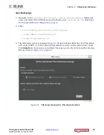
Page 22: ...page 9 2 Enter cd working_dir kcu105_control_plane sudo chmod x quickstart sh sudo sh quickstart sh 3 The TRD setup screen is displayed Figure 3 8 and indicates detection of a PCIe device with an ID of 8011 a control plane design selection and a control plane driver mode Click Install and the drivers are installed This takes you to the Control and Monitoring GUI as shown in Figure 3 12 page 26 X R...

Page 23: ...r booting the Windows OS follow these steps 1 Repeat the steps in section Disable Driver Signature Enforcement page 9 2 Open Device Manager click Start devmgmt msc then press Enter and look for the Xilinx PCI Express Device as shown in Figure 3 9 X Ref Target Figure 3 9 Figure 3 9 Xilinx PCI Express Device in Device Manager UG918_c3_11_040715 Send Feedback ...
Page 24: ...G918 v2017 2 July 18 2017 Chapter 3 Bringing Up the Design 3 Open a command prompt with administrator privileges as shown in Figure 3 10 X Ref Target Figure 3 10 Figure 3 10 Command Prompt with Administrator Privileges UG918_c3_12_040715 Send Feedback ...

Page 25: ... dir kcu105_control_plane 5 Run the batch script quickstart_win7 bat quickstart_win7 bat 6 The screen in Figure 3 11 shows the TRD Setup screen of the GUI Click Proceed to test the reference design This step takes you to the Control and Monitoring GUI as shown in Figure 3 12 page 26 X Ref Target Figure 3 11 Figure 3 11 GUI TRD Setup Screen UG918_c3 13_040715 Send Feedback ...
Page 26: ...BAR4 by providing the offset value and data value to be written Obtain a dump of the data from a specific address offset from BAR4 You can view the block diagram by clicking Block Diagram in top right corner of the screen Figure 3 12 Click the X mark on the top right corner to close the GUI On a Linux host computer this step uninstalls the drivers and returns the GUI to the TRD Setup screen Close ...

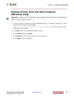
Page 27: ...following steps to remove the Windows drivers 1 Power on the host computer and from Windows Explorer navigate to the folder in which the reference design is downloaded dir kcu105_control_plane software windows Run the setup file with administrator privileges 2 Click Next after the InstallShield Wizard opens 3 Select Remove and click Next 4 Click Remove to remove drivers from the host system 5 Clic...

Page 28: ...tation Refer to Refer to the following AR for more details KCU105 Evaluation Kit Master Answer Record AR 63175 Implementing the Base Design 1 If not already done so copy the reference design ZIP file to the desired directory on the control PC and unzip the ZIP file The TRD files were extracted to your working_dir in Download the Targeted Reference Design Files page 9 2 Open a terminal window on a ...

Page 29: ...ress Control Plane TRD www xilinx com 29 UG918 v2017 2 July 18 2017 Chapter 4 Implementing and Simulating the Design X Ref Target Figure 4 1 Figure 4 1 Base Design Project View UG918_c4_01_070717 Send Feedback ...

Page 30: ...hich runs synthesis implementation and generates the BIT file see Figure 4 2 Click Yes if a window indicating No Implementation Results are available is displayed The generated bitstream can be found under the following directory kcu105_control_plane hardware vivado runs_base trd01 runs impl_1 X Ref Target Figure 4 2 Figure 4 2 Base Design Generate Bitstream UG918_c4_02_070717 Send Feedback ...
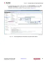
Page 31: ...t up or open a Vivado tools Tcl shell on a Windows system 2 Navigate to the kcu105_control_plane hardware vivado scripts user_extn folder 3 To run the implementation flow enter vivado source trd01_user_extn tcl This opens the Vivado IDE loads the block diagram and adds the required top file and XDC file to the project see Figure 4 3 X Ref Target Figure 4 3 Figure 4 3 User Extension Design Project ...

Page 32: ...vivado runs_user_extn trd01 runs impl_1 Simulating the Base Design Using Vivado Simulator The targeted reference design can be simulated using the Vivado simulator The testbench and the Endpoint PCIe IP block are configured to use the PHY Interface for PCI Express PIPE mode simulation The test bench initializes the bridge does one double word DW write to BAR mapped address space reads back from th...

Page 33: ...ator 1 Open a terminal window on a Linux system with the Vivado environment set up or open a Vivado tools Tcl shell on a Windows system 2 Navigate to the kcu105_control_plane hardware vivado scripts base folder 3 To run simulation enter vivado source trd01_base tcl This opens the Vivado IDE with the target simulator set to the Vivado Simulator Figure 4 5 X Ref Target Figure 4 5 Figure 4 5 Base Des...

Page 34: ...vigator panel under Simulation click Run Simulation and select Run Behavioral Simulation This generates all the simulation files loads the Vivado simulator and runs the simulation The result is shown in Figure 4 6 X Ref Target Figure 4 6 Figure 4 6 Base Design Behavioral Simulation using the Vivado Simulator UG918_c4_06_070717 Send Feedback ...

Page 35: ...D hardware design components Subsequent sections discuss each of the components in detail X Ref Target Figure 5 1 Figure 5 1 TRD Functional Block Diagram 352 6625 5RRW RPSOH 3 H ULGJH 6ODYH 0DVWHU 3 H ULYHU HUQHO VSDFH 3 H HQ LQN 397021 5HJLVWHUV 3 5 6 6021 ELWV DW 0 8 7 QWHJUDWHG 3 H ORFN 3 H 3 UDSSHU QWHJUDWHG EORFN RQ 3 LOLQ LQ KRXVH 3 XVWRP ORJLF LQ 3 6RIWZDUH UXQQLQJ RQ KRVW FRPSXWHU RPSRQHQW...

Page 36: ...ided with the design is an evaluation version of the IP It times out in hardware after 12 hours To obtain a full license of the IP contact Northwest Logic AXI PCIe Bridge The AXI PCIe bridge translates protocol to support transactions between the PCIe and AXI3 domains It provides support for two ingress translation regions to convert PCIe BAR mapped transactions to AXI3 domain transactions Bridge ...

Page 37: ...es with separate source and destination DMA completion Status queues DMA channels merge the source and destination scatter gather information AXI Block RAM Controller The AXI block RAM controller provides block RAM with an AXI4 memory mapped interface This behaves as a register file in this design to which BAR mapped transactions are targeted See LogiCORE IP AXI Block RAM BRAM Controller Product G...

Page 38: ...SYSMON registers in continuous sequence mode and read various rail data periodically The output from PicoBlaze is made available in block RAM and an FSM reads various rails from the block RAM as shown in Figure 5 2 and updates the user space registers These registers can be accessed over PCIe through the BAR mapped region The AXI4 Lite IPIF core is used in the design and the interface logic betwee...

Page 39: ... write functionality 2 The GUI issues WRITE system calls for writing into BAR mapped registers based on your input 3 The driver writes appropriate values into BAR mapped registers Receive Path 1 The GUI issues a READ system call to read BAR mapped registers based on your input 2 The Character driver reads appropriate BAR mapped registers and conveys the readings to the GUI 3 The GUI displays the r...

Page 40: ... can be designed with the existing blocks Graphical User Interface The user space GUI is a Java based GUI that provides these features GUI management of the driver and device In Linux the GUI installs the selected design mode drivers and can configure and control device and test parameters In Windows the GUI can configure and control device and test parameters X Ref Target Figure 5 3 Figure 5 3 TR...

Page 41: ...s provided that can be run to generate a bitstream with an additional AXI block RAM controller added The additional block RAM is mapped to AXI address 0xD000_0000 The steps needed to build the user modification design are described in Chapter 4 Implementing and Simulating the Design Software Modification IMPORTANT The pre built user extention design can be tested only on Linux and not on Windows T...

Page 42: ...ntrollers an additional ingress translation aperture can be mapped and the ReadUserReg function in the driver can be used to access those registers The display from the software driver can be seen in the system dmesg log The ability to read multiple user registers or block RAM controllers is not supported by the GUI and the aperture size is currently limited to 4K Send Feedback ...

Page 43: ...he TRD is shown in Figure A 1 and described in Table A 1 For a detailed description of each folder see the Readme file X Ref Target Figure A 1 Figure A 1 TRD Directory Structure KDUGZDUH VRXUFHV UHDG BWRBWHVW OLQX BGULYHUBDSS VRIWZDUH UHDGPH kcu105_control_plane YLYDGR KGO FRQVWUDLQWV LSBSDFNDJH WHVWEHQFK 8 BD B B ZLQGRZV Send Feedback ...

Page 44: ...tations of the design if any hardware Contains hardware design deliverables sources hdl Contains HDL files constraints Contains constraint files ip_package Contains custom IP packages testbench Contains test bench files vivado Contains scripts to create a Vivado Design Suite project and outputs of Vivado runs ready to test Contains the BIT file to program the KCU105 PCI Express Control Plane appli...

Page 45: ... see if the drivers are loaded under Xilinx PCI Express Device 2 If the drivers are not loaded check the PCIe Link Up LED on the board see Figure 3 6 3 If the drivers are loaded but the GUI is not detecting the board remove non present devices from Device Manager using the following steps a Open a command prompt with Administrator privileges b At the command prompt enter the following bold text se...

Page 46: ...lude design assistance advisories and troubleshooting tips References The most up to date information for this design is available on these websites KCU105 Evaluation Kit website KCU105 Evaluation Kit documentation KCU105 Evaluation Kit Master Answer Record AR 63175 These documents and sites provide supplemental material 1 Northwest Logic Expresso DMA Bridge Core 2 Vivado Design Suite User Guide R...

Page 47: ...THOUT A SAFETY DESIGN IS FULLY AT THE RISK OF CUSTOMER SUBJECT ONLY TO APPLICABLE LAWS AND REGULATIONS GOVERNING LIMITATIONS ON PRODUCT LIABILITY Fedora Information Xilinx obtained the Fedora Linux software from Fedora http fedoraproject org and you may too Xilinx made no changes to the software obtained from Fedora If you desire to use Fedora Linux software in your product Xilinx encourages you t...

Reviews: