10GBASE-KR Ethernet TRD
39
UG1058 (v2017.1) April 19, 2017
Chapter 3:
Bringing Up the Design
2. Repeat
3. Repeat
and
.
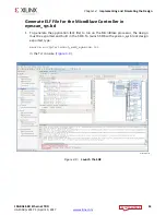
4. Program the FPGA:
a. In the
Bitstream file
field, browse to the location of the BIT file:
<working_dir>/kcu1250_10gbasekr_trd/ready_to_test/fec_and_err_
injection/kcu1250_10gbasekr_download.bit
b. In the
Debug Probes file
field, browse to the location of the LTX file:
<working_dir>/kcu1250_10gbasekr_trd/ready_to_test/
fec_and_err_injection/debug_nets.ltx
c. Click
Program
(
).
There are seven VIO cores in the reference design. After programming, they can be
controlled in the Vivado IDE. To add probes to each VIO window:
1. Open the VIO dashboard. On the top panel of the Vivado IDE, click
Window >
Dashboard > Reset to default.
2. Open the Debug Probes window: on the top panel of the Vivado IDE click
Window >
Debug Probes
.
3. In the Debug Probes window, right click on
hw_vio_1
and select
Add probes to VIO
Window
.
4. Repeat the same procedure for hw_vio_2, hw_vio_3, hw_vio_4, hw_vio_5, hw_vio_6, and
hw_vio_7.
X-Ref Target - Figure 3-21
Figure 3-21:
Program Device Window
X18461-120716

