10GBASE-KR Ethernet TRD
21
UG1058 (v2017.1) April 19, 2017
Chapter 3:
Bringing Up the Design
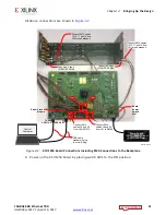
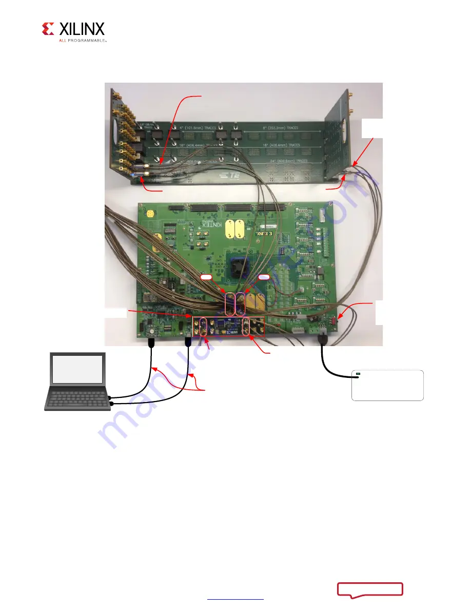
All above connections are shown in
.
8. Power on the KCU1250 board by placing switch SW1 to the ON position.
X-Ref Target - Figure 3-2
Figure 3-2:
KCU1250 Board Connections Including SMA Connections to the Backplane
Power Supply
100VAC–240VAC Input
12 VDC 5.0A Output
Board
Power
Switch
SW1
To U80
USB JTAG
J1
USB UART
USB cable
standard-A plug
to micro-B plug
Connect SMA cables
15,16,17 and 18 from
J42 to the backpane
Connect SMA cables
15,16,17 and 18 from
J41 to the backpane
Connect AC caps
toTXN/TXP SMAs
Connect AC caps
toTXN/TXP SMAs
Connect SMA
cables 19 and 20
from J41 to Si5368
Connect SMA
cables 19 and 20
from J42 to Si570
Super-Clock II
Module
J41
J42
Wally
&RQWURO
&RPSXWHU
X18442-120716


