6
KC724 GTX Transceiver Characterization Board
UG932 (v2.2) October 10, 2014
Chapter 1:
KC724 Board Features and Operation
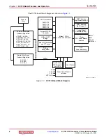
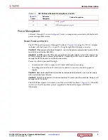
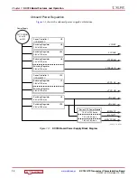
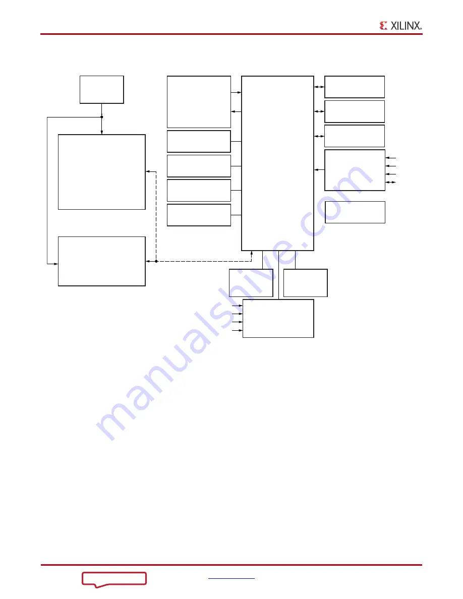
The KC724 board block diagram is shown in
X-Ref Target - Figure 1-1
Figure 1-1:
KC724 Board Block Diagram
UG9
3
2_c1_01_092912
FPGA Power
S
o
u
rce
On-
b
o
a
rd Reg
u
l
a
tion:
Bo
a
rd Utility Power
On-
b
o
a
rd Reg
u
l
a
tion:
P
us
h B
u
tton
s
,
DIP
S
witche
s
,
a
nd LED
s
Su
perClock-2 Mod
u
le
Interf
a
ce
GTX Tr
a
n
s
ceiver
s
QUAD 115
QUAD 116
QUAD 117
QUAD 118
Kintex-7 FPGA
XC7K
3
25T-
3
FFG900E
S
elect I/O Termin
a
tion
a
nd VTT J
a
ck
s
An
a
log/Digit
a
l
Converter (XADC)
FMC1 Interf
a
ce
High-Perform
a
nce I/O
U
S
B to UART
Bridge
FMC2 Interf
a
ce
High-R
a
nge I/O
I
2
C B
us
M
a
n
a
gement
7
S
erie
s
GTX Power Mod
u
le
Interf
a
ce
12V
PMB
us
5V
3
.
3
V
U
s
er Clock
s
S
y
s
tem ACE
S
D
Controller
Power In
12V
DC
PMB
us
VCCINT 1.0V, 20A
VCCBRAM 1.0V, 10A
VCCAUX 1.8V, 10A
VCCAUX_IO 1.8V, 10A
VCCO_HP 1.8V, 10A
VCCO_HR 1.8V, 10A
VCCO_0 2.5V, 7.5A
5.0V, 10A
3
.
3
V, 18A
2.5V, 1.5A
GTX
Power Monitoring
VCCO_HR
5V
3
.
3
V
2.5V

