10
KC724 GTX Transceiver Characterization Board
UG932 (v2.2) October 10, 2014
Chapter 1:
KC724 Board Features and Operation
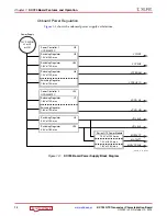
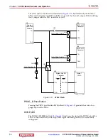
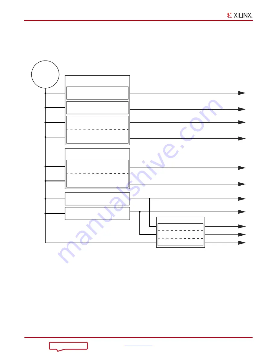
Onboard Power Regulation
shows the onboard power supply architecture.
X-Ref Target - Figure 1-3
Figure 1-3:
KC724 Board Power Supply Block Diagram
UG9
3
2_c1_0
3
_072712
MGTVCCAUX
MGTAVTT
MGTAVCC
VCCAUX
VCCINT
VCCAUX_IO
VCCBRAM
VCCO_HR
VCCO_HP
Power
Su
pply
12V PWR IN
J2 or J5
or J1
3
1
Power Controller 1
UCD9248PFC
U9
S
witching Reg
u
l
a
tor
1.0V
a
t 20A m
a
x
U5
S
witching Reg
u
l
a
tor
1.8V
a
t 10A m
a
x
U6
S
witching Reg
u
l
a
tor
1.0V
a
t 10A m
a
x
S
witching Reg
u
l
a
tor
1.8V
a
t 10A m
a
x
U24
Power Controller 2
UCD9248PFC
U10
S
witching Reg
u
l
a
tor
1.8V
a
t 10A m
a
x
U7
S
witching Reg
u
l
a
tor
1.8V
a
t 10A m
a
x
S
witching Reg
u
l
a
tor
5.0V
a
t 10A m
a
x
U2
S
witching Reg
u
l
a
tor
3
.
3
V
a
t 18A m
a
x
U1
3
UTIL_5V0
UTIL_
3
V
3
7
S
erie
s
GTX Power Mod
u
le
1.05V
a
t 12.0A m
a
x
1.2V
a
t 8.0A m
a
x
1.8V
a
t 2.6A m
a
x


