KC724 GTX Transceiver Characterization Board
13
UG932 (v2.2) October 10, 2014
Detailed Description
Disabling Onboard Power
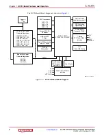
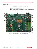
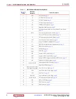
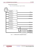
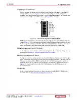
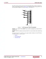
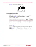
Each core power regulator can be disabled through the 8-position regulator enable DIP
switch, SW10 as shown in
. A switch in the ON position means the rail is
supplied by an onboard regulator. Setting a switch in the opposite (OFF) position disables
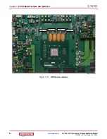
onboard power for that rail. SW10 is shown in
as callout
Note:
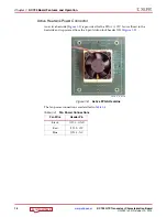
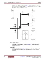
All onboard power can be disabled by placing a jumper across the TI PWR INH header J27
(callout
). For the purposes of supplying external core power however, disabling onboard
power through J27 would require the UTIL_5V0, UTIL_3V3 and UTIL_2V5 be supplied externally as
well. The utility rails can be supplied through test points J5
8
, J59 and J155, respectively.
Default Jumper and Switch Positions
A list of jumpers and switches and their required positions for normal board operation is
provided in
Appendix A, Default Jumper and Switch Positions
.
Monitoring Voltage and Current
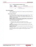
Voltage and current monitoring and control are available for selected power rails through
Texas Instruments' Fusion Digital Power graphical user interface (GUI). The three onboard
TI power controllers (U9 at PMBUS address 52, U10 at PMBUS address 53, and U11 at
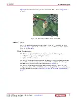
PMBUS address 54) are wired to the same PMBus. The PMBus connector, J26 (callout
), is provided for use with the TI USB Interface Adapter PMBus pod and
associated TI GUI.
References
More information about the power system components used by the KC724 board are
available from the
Texas Instruments Digital Power website
X-Ref Target - Figure 1-5
Figure 1-5:
Core Power Regulator Enable Switches
SW10
1
234
5
NC
NC
VCCO_HR
VCCO_HP
VCCAUX_IO
ON
67
8
VCCBRAM
VCCAUX
VCCINT
Pin 1
UG932_c1_05_062812


