AXI Bridge for PCI Express v2.4
53
PG055 June 4, 2014
Chapter 3:
Designing with the Core
Example 1 (32-bit PCIe Address Mapping)
This example shows the generic settings to set up four independent 32-bit AXI BARs and
address translation of AXI addresses to a remote address space for PCIe. This setting of AXI
BARs does not depend on the BARs for PCIe within the AXI Bridge for PCI Express core.
In this example, where C_AXIBAR_NUM=4, the following assignments for each range are
made:
C_AXIBAR_AS_0=0
C_AXIBAR_0=0x12340000
C_AXI_HIGHADDR_0=0x1234FFFF
C_AXIBAR2PCIEBAR_0=0x5671XXXX (Bits 15-0 do not matter as the lower 16-bits hold the
actual lower 16-bits of the PCIe address)
C_AXIBAR_AS_1=0
C_AXIBAR_1=0xABCDE000
C_AXI_HIGHADDR_1=0xABCDFFFF
C_AXIBAR2PCIEBAR_1=0xFEDC0XXX (Bits 12-0 do not matter as the lower 13-bits hold the
actual lower 13-bits of the PCIe address)
C_AXIBAR_AS_2=0
C_AXIBAR_2=0xFE000000
C_AXI_HIGHADDR_2=0xFFFFFFFF
C_AXIBAR2PCIEBAR_2=0x40XXXXXX (Bits 24-0 do not care)
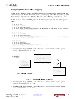
• Accessing the Bridge AXIBAR_0 with address
0x12340ABC
on the AXI bus yields
0x56710ABC
on the bus for PCIe.
• Accessing the Bridge AXIBAR_1 with address
0xABCDF123
on the AXI bus yields
0xFEDC1123
on the bus for PCIe.
• Accessing the Bridge AXIBAR_2 with address
0xFFFEDCBA
on the AXI bus yields
0x41FEDCBA
on the bus for PCIe.
X-Ref Target - Figure 3-7
Figure 3-7:
AXI to PCIe Address Translation
X
X&&&&
X!"#
INAL 0#)E !DDRESS
)NTERMEDIATE !DDRESS X!"#
8
!8)!7!$$2
#?!8)"!20#)%"!2?XXXXX
#?!8)"!2?
#?!8)?()'(!$$2?
&
X!"#
!"#
!8)TO0#)E!DDRESS4RANSLATION


