AXI Bridge for PCI Express v2.4
81
PG055 June 4, 2014
Chapter 5:
Example Design
Note:
The example design supports Verilog as the target language.
Customizing and Generating the Example Design
In Customize IP dialog box, make the following selections for the example design.
1. In the PCIE:Basics page, the example design supports only an Endpoint (EP) device.
2. The PCIE:ID defaults are supported.
3. The PCIE:BARS defaults are supported.
4. The PCIE:Misc page defaults are supported.
5. In the AXI:BARS page, default values are assigned to the Base Address, High Address,
and AXI to PCIe Translation values.
6. The AXI:System page default values are supported:
Note:
After customizing the core, right-click the component name, and select
Open IP Example
Design
. This opens a separate example design. Simulate the core by following the steps in the next
section.
Simulating the Example Design
The example design can be run in any configuration using:
• Vivado Simulator
• Cadence IES Simulator
• Mentor Graphics Questa® SIM
• VCS Simulator
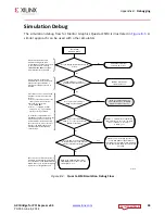
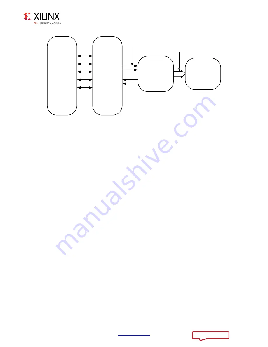
X-Ref Target - Figure 5-1
Figure 5-1:
Example Design Block Diagram
7UDIILF
*HQHUDWRU
3&,HJHQ
6WUHDPLQJ
&RUH53
$;,3&,H(3
$;,%5$0
&RQWUROOHU
LQEXLOW%5$0
$;,,)
3&,H/LQN
;


