Cable Hardware
Hardware User Guide
1-21
•
Provide appropriate pins on your printed circuit board for your
device type.
•
Place pins on board so that flying leads can reach them. The
flying leads that are shipped with the cable are six inches long.
While pins may be a couple inches apart, do not have any two
pins more than six inches apart.
•
Keep header pins on your board a minimum of 0.10 inches apart.
Cable Connection Procedure
The following steps are required for download cable operation.
1.
Connect the cable to your host system. Make sure to use the
appropriate port and adapter, if necessary.
2.
Connect the cable to your target system or demonstration board.
Always power up the host system before the target system. The
power for the drivers is derived from the target system.
3.
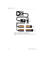
Connect the cable’s GND wire to the corresponding signal on the
target board. Next, connect VCC to the +5 V on the target board.
4.
Connect the appropriate pins for device configuration.
5.
Power up the target system.
Cable protection ensures that the host system port cannot be
damaged through normal cable operation. For increased safety,
please check that the power to the host computer is on before the
target system is powered up.
6.
Start the appropriate Xilinx software package and configure your
device. The JTAG Programmer Software and Hardware
Debugger Software will automatically identify the download
cables when correctly connected. If you need to set up the cable
manually, see the following section.
Note
The download cables will not operate if the target system‘s
power is turned off before or during software operations. Make
certain that this power connection is on and stable. Your system’s
power should be on during ISP operations. When powering
down, turn off the target demonstration board first, and then the
host machine.


