background image

SP623
Spartan-6 FPGA
GTP Transceiver
Characterization Board

User Guide

UG751 (v1.0) May 22, 2010

Summary of Contents for SP623

Page 1: ...SP623 Spartan 6 FPGA GTP Transceiver Characterization Board User Guide UG751 v1 0 May 22 2010...

Page 2: ...s Xilinx expressly disclaims any liability in connection with technical support or assistance that may be provided to you in connection with the Information THE DOCUMENTATION IS DISCLOSED TO YOU AS IS...

Page 3: ...ED 15 INIT LED 15 System ACE Controller 16 System ACE Controller Reset 16 Configuration Address DIP Switches 16 JTAG Isolation Jumpers 16 200 MHz 2 5V LVDS Oscillator 17 SuperClock 2 Module 17 User SM...

Page 4: ...4 www xilinx com SP623 Board User Guide UG751 v1 0 May 22 2010...

Page 5: ...ons lists the jumpers that must be installed on the board for proper operation Appendix B VITA 57 1 FMC HPC Connector Pinout provides a pinout reference for the FPGA mezzanine card FMC connector Appen...

Page 6: ...le Open Keyboard shortcuts Ctrl C Italic font Variables in a syntax statement for which you must supply values ngdbuild design_name References to other manuals See the Command Line Tools User Guide fo...

Page 7: ...on port for use with Platform Cable USB or Parallel Cable III IV cables System ACE controller Power module supporting all Spartan 6 FPGA GTP transceiver power requirements A fixed 200 MHz 2 5V LVDS os...

Page 8: ...Diagram UG751_c1_01_050410 Spartan 6 FPGA XC6SLX150T 3FGG676 Power In 12V FMC Interface FMC1 and FMC2 ANSI VITA 57 1 2008 v1 1 USB to UART Bridge System ACE Controller I2C Bus Management GTP Transcei...

Page 9: ...on jumpers J30 J31 J33 J102 J104 J105 11 SuperClock 2 module 1e Regulation inhibit J14 J19 12 User SMA global clock inputs J167 J168 1f External power supply jacks 13 User LEDs active High DS10 DS17 1...

Page 10: ...using the 12V AC adapter included with the board J122 is a 6 pin 2 x 3 right angle Mini Fit type connector Power can also be provided through Connector J141 which accepts an ATX hard disk 4 pin power...

Page 11: ...oltage See Using External Power Sources X Ref Target Figure 1 3 Figure 1 3 SP623 Board Power Supply Block Diagram External Supply Jacks VCCINT VCCAUX VCCO VCC2V5 UG751_c1_03_041510 VCC3V3 VCC5 Power S...

Page 12: ...a jumper across pins 2 3 of header J19 Default Jumper Positions A list of shunts and shorting plugs and their required positions for normal board operation is provided in Appendix A Default Jumper Po...

Page 13: ...h the SP623 board Either of the power modules can be plugged into connectors J34 and J179 in the outlined and labeled power module location shown in Figure 1 4 Table 1 2 describes the nominal voltage...

Page 14: ...ing the power supply output to J5 FPGA Configuration Figure 1 2 callout 2 The FPGA is configured in JTAG mode only using one of the following options Platform Cable USB Parallel Cable IV Parallel Cabl...

Page 15: ...lout 3 Pressing the PROG push button SW5 grounds the active Low program pin of the FPGA DONE LED Figure 1 2 callout 4 The DONE LED DS6 indicates the status of the DONE pin of the FPGA When the DONE pi...

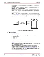
Page 16: ...selects one of the eight configuration bitstream addresses in the CompactFlash memory card The switch settings for selecting each address are identified in Table 1 3 JTAG Isolation Jumpers Figure 1 2...

Page 17: ...dule interface connector J32 and provides a programmable low noise clock source for the SP623 board The clock module maps to FPGA I O by way of 24 control pins 3 LVDS pairs 1 regional clock pair and 1...

Page 18: ...CM_GCLK_P 25 U26 CM_GCLK_N 27 U20 CM_CTRL_0 61 U19 CM_CTRL_1 63 AA24 CM_CTRL_2 65 AA23 CM_CTRL_3 67 T20 CM_CTRL_4 69 T19 CM_CTRL_5 71 U22 CM_CTRL_6 73 U21 CM_CTRL_7 75 AE26 CM_CTRL_8 77 AE25 CM_CTRL_...

Page 19: ...t 13 DS10 through DS17 are eight active High LEDs that are connected to user I O on the FPGA as shown in Table 1 8 These LEDs can be used to indicate status or any other purpose determined by the user...

Page 20: ...Figure 1 2 callout 16 A standard 2 x 6 100 mil pitch header J44 brings out 6 FPGA I O for test purposes Table 1 11 lists these pins Table 1 9 User DIP Switches FPGA Pin Net Name Reference Designator...

Page 21: ...e clock pin pairs Figure 1 8 The transceiver pins and their corresponding SMA connector are identified in Table 1 12 X Ref Target Figure 1 8 Figure 1 8 GTP Transceiver and Reference Clock SMA Location...

Page 22: ...3 2 939 A20 123_TX1_N J62 2 941 AC8 245_RX0_P J48 4 316 AD8 245_RX0_N J73 4 315 AE7 245_TX0_P J74 3 616 AF7 245_TX0_N J75 3 615 AC10 245_RX1_P J76 3 865 AD10 245_RX1_N J77 3 865 AE9 245_TX1_P J78 2 56...

Page 23: ...Laboratories CP2103 Table 1 14 lists the pin assignments and signals for the USB connector J9 Table 1 13 GTP Transceiver Clock Inputs to the FPGA FPGA Pin Net Name SMA Connector B10 101_REFCLK0_P J59...

Page 24: ...puter communications application software for example HyperTermimal or TeraTerm The VCP driver must be installed on the host computer prior to establishing communications with the SP623 board FMC HPC...

Page 25: ...capable of supporting 2 5V VADJ The connections for the FMC1 and FMC2 connectors are identified in Table 1 17 and Table 1 18 respectively Table 1 17 Vita 57 1 FMC1 HPC Connections at J112 FPGA Pin Net...

Page 26: ...MC1_HA14_N J16 M8 FMC1_HA15_P F16 M6 FMC1_HA15_N F17 K5 FMC1_HA16_P E15 J5 FMC1_HA16_N E16 L7 FMC1_HA17_CC_P K16 L6 FMC1_HA17_CC_N K17 B2 FMC1_HA18_P J18 B1 FMC1_HA18_N J19 L10 FMC1_HA19_P F19 K10 FMC...

Page 27: ...1_LA06_P C10 G7 FMC1_LA06_N C11 H10 FMC1_LA07_P H13 G10 FMC1_LA07_N H14 B4 FMC1_LA08_P G12 A4 FMC1_LA08_N G13 F10 FMC1_LA09_P D14 E10 FMC1_LA09_N D15 B5 FMC1_LA10_P C14 A5 FMC1_LA10_N C15 H8 FMC1_LA11...

Page 28: ...A22_P G24 E18 FMC1_LA22_N G25 G16 FMC1_LA23_P D23 F17 FMC1_LA23_N D24 F20 FMC1_LA24_P H28 E20 FMC1_LA24_N H29 H17 FMC1_LA25_P G27 G17 FMC1_LA25_N G28 C21 FMC1_LA26_P D26 B21 FMC1_LA26_N D27 G6 FMC1_LA...

Page 29: ...pin 13 Table 1 18 Vita 57 1 FMC2 HPC Connections at J113 FPGA Pin Net Name FMC Pin U23 FMC2_CLK0_M2C_P H4 U24 FMC2_CLK0_M2C_N H5 AD14 FMC2_CLK1_M2C_P G2 AF14 FMC2_CLK1_M2C_N G3 R7 FMC2_HA00_CC_P F4 R...

Page 30: ...MC2_HA15_P F16 P6 FMC2_HA15_N F17 P5 FMC2_HA16_P E15 R5 FMC2_HA16_N E16 N8 FMC2_HA17_CC_P K16 N7 FMC2_HA17_CC_N K17 R4 FMC2_HA18_P J18 R3 FMC2_HA18_N J19 R9 FMC2_HA19_P F19 P8 FMC2_HA19_N F20 N5 FMC2_...

Page 31: ...6_N C11 AA19 FMC2_LA07_P H13 AB19 FMC2_LA07_N H14 W16 FMC2_LA08_P G12 Y16 FMC2_LA08_N G13 AA18 FMC2_LA09_P D14 AB17 FMC2_LA09_N D15 Y15 FMC2_LA10_P C14 AA16 FMC2_LA10_N C15 V14 FMC2_LA11_P H16 V15 FMC...

Page 32: ..._LA22_N G25 AD6 FMC2_LA23_P D23 AF6 FMC2_LA23_N D24 W20 FMC2_LA24_P H28 Y20 FMC2_LA24_N H29 W10 FMC2_LA25_P G27 W9 FMC2_LA25_N G28 AE5 FMC2_LA26_P D26 AF5 FMC2_LA26_N D27 Y9 FMC2_LA27_P C26 AA8 FMC2_L...

Page 33: ...he MUX as shown in Table 1 20 AC3 FMC2_PRSNT_M2C H2 U20 13 FMC2_TCK_BUF 1 D29 J36 1 FMC2_TDI 1 D30 J36 3 FMC2_TDO 1 D31 U20 16 TMS_BUF 1 D33 Notes 1 This signal is not directly connected to the FPGA T...

Page 34: ...34 www xilinx com SP623 Board User Guide UG751 v1 0 May 22 2010 Chapter 1 SP623 Board Features and Operation...

Page 35: ...me Shunt Position Quantity Pins Jumper Label J14 TI PWR INH Installed 1 1 2 AFX MB J38 UCD9240 CTRL PIN Installed 1 1 2 ALWAYS ON J33 VCC5 REG ENABLE 1 Installed Horizontally 2 1 2 3 4 J19 VCC5 REG IN...

Page 36: ...ries are not visible in the PCB silkscreen labels Table A 1 Standard Shunts Cont d Connector Name Shunt Position Quantity Pins Jumper Label Table A 2 Digital Power Shorting Plugs Connector Name Shorti...

Page 37: ...GND DP3_C2M_P DP3_C2M_N GND GND DP4_C2M_P DP4_C2M_N GND GND DP5_C2M_P DP5_C2M_N GND RES1 GND GND DP9_M2C_P DP9_M2C_N GND GND DP8_M2C_P DP8_M2C_N GND GND DP7_M2C_P DP7_M2C_N GND GND DP6_M2C_P DP6_M2C_...

Page 38: ...38 www xilinx com SP623 Board User Guide UG751 v1 0 May 22 2010 Appendix B VITA 57 1 FMC HPC Connector Pinout...

Page 39: ...J112 and J113 are connected to 2 5V Vcco banks Because each user s FMC card implements customer specific circuitry the FMC bank I O standards must be uniquely defined by each customer SP623 Master UC...

Page 40: ...4 NET CM_CTRL_12 LOC AC26 NET CM_CTRL_13 LOC AC25 NET CM_CTRL_14 LOC AB26 NET CM_CTRL_15 LOC AB24 NET CM_CTRL_16 LOC AD26 NET CM_CTRL_17 LOC AD24 NET CM_CTRL_18 LOC AA26 NET CM_CTRL_19 LOC AA25 NET CM...

Page 41: ...ET FMC1_HA05_P LOC K3 NET FMC1_HA06_N LOC J1 NET FMC1_HA06_P LOC J2 NET FMC1_HA07_N LOC H1 NET FMC1_HA07_P LOC H3 NET FMC1_HA08_N LOC G1 NET FMC1_HA08_P LOC G2 NET FMC1_HA09_N LOC F1 NET FMC1_HA09_P L...

Page 42: ...LA11_N LOC G8 NET FMC1_LA11_P LOC H8 NET FMC1_LA12_N LOC G11 NET FMC1_LA12_P LOC J11 NET FMC1_LA13_N LOC G13 NET FMC1_LA13_P LOC H12 NET FMC1_LA14_N LOC J12 NET FMC1_LA14_P LOC K12 NET FMC1_LA15_N LOC...

Page 43: ...2_HA05_N LOC T6 NET FMC2_HA05_P LOC U7 NET FMC2_HA06_N LOC AB1 NET FMC2_HA06_P LOC AB3 NET FMC2_HA07_N LOC AD1 NET FMC2_HA07_P LOC AD3 NET FMC2_HA08_N LOC AC1 NET FMC2_HA08_P LOC AC2 NET FMC2_HA09_N L...

Page 44: ...MC2_LA10_P LOC Y15 NET FMC2_LA11_N LOC V15 NET FMC2_LA11_P LOC V14 NET FMC2_LA12_N LOC V13 NET FMC2_LA12_P LOC U13 NET FMC2_LA13_N LOC AB15 NET FMC2_LA13_P LOC AA15 NET FMC2_LA14_N LOC AA22 NET FMC2_L...

Page 45: ...LOC V3 NET IO_L40N_M3DQ7_3_U1 LOC U1 NET IO_L40P_M3DQ6_3_U2 LOC U2 NET IO_LVDS_CLK_N LOC W24 NET IO_LVDS_CLK_P LOC V23 NET LED1 LOC L21 NET LED2 LOC L20 NET LED3 LOC M23 NET LED4 LOC M21 NET LED5 LOC...

Page 46: ...46 www xilinx com SP623 Board User Guide UG751 v1 0 May 22 2010 Appendix C SP623 Master UCF Listing...

Page 47: ...380 Spartan 6 FPGA Configuration User Guide UG385 Spartan 6 FPGA Packaging and Pinout Specifications UG381 Spartan 6 FPGA SelectIO Resources User Guide UG388 Spartan 6 FPGA Memory Controller User Guid...

Page 48: ...48 www xilinx com SP623 Board User Guide UG751 v1 0 May 22 2010 Appendix D References...

Reviews: