background image

20

www.xilinx.com

Spartan-6 FPGA PCB Design and Pin Planning

UG393 (v1.1) April 29, 2010

Chapter 2:

Power Distribution System

Basic PDS Principles

The purpose of the PDS and the properties of its components are discussed in this section. 
The important aspects of capacitor placement, capacitor mounting, PCB geometry, and 
PCB stackup recommendations are also described.

Noise Limits

In the same way that devices in a system have a requirement for the amount of current 
consumed by the power system, there is also a requirement for the cleanliness of the 
power. This cleanliness requirement specifies a maximum amount of noise present on the 
power supply, often referred to as ripple voltage (V

RIPPLE

). Most digital devices, including 

all Spartan-6 FPGAs, require that V

CC 

supplies not fluctuate more than ±5% of the nominal 

V

CC

 value. This means that the peak-to-peak V

RIPPLE

 must be no more than 10% of the 

nominal V

CC

. In this document the term V

CC

 is used generically for the following FPGA 

power supplies: V

CCINT

, V

CCO

, V

CCAUX

, and V

REF

. This assumes that nominal V

CC

 is 

exactly the nominal value provided in the data sheet.


If not, then V

RIPPLE

 must be adjusted 

to a value correspondingly less than 10%.

The power consumed by a digital device varies over time and this variance occurs on all 
frequency scales, creating a need for a wide-band PDS to maintain voltage stability.

Low-frequency variance of power consumption is usually the result of devices or 
large portions of devices being enabled or disabled. This variance occurs in time 
frames from milliseconds to days.

High-frequency variance of power consumption is the result of individual switching 
events inside a device. This occurs on the scale of the clock frequency and the first few 
harmonics of the clock frequency up to about 1 GHz.

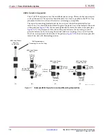
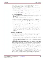
X-Ref Target - Figure 2-2

Figure 2-2:

Example 0402 Capacitor Land and Mounting Geometries

0402 L

a

nd P

a

ttern

End Vi

as

Long Tr

a

ce

s

(A)

(C)

(B)

(D)

UG

3

9

3

_c2_02_091

8

09

0402 L

a

nd P

a

ttern

End Vi

as

0.

38

1 mm

(15 mil

s

)

0.6

3

5 mm

(25 mil

s

)

1.07 mm
(42 mil

s

)

0.61mm
(24 mil

s

)

0402 L

a

nd P

a

ttern

Do

ub

le 

S

ide Vi

as

0.762 mm
(

3

0 mil

s

)

0.

38

1 mm

(15 mil

s

)

0.61mm
(24 mil

s

)

0402 L

a

nd P

a

ttern

S

ide Vi

as

0.762 mm
(

3

0 mil

s

)

0.

38

1 mm

(15 mil

s

)

0.61mm
(24 mil

s

)

Not Recommended.

Connecting Tr

a

ce is Too Long

Summary of Contents for Spartan-6 FPGA Series

Page 1: ...Spartan 6 FPGA PCB Design and Pin Planning Guide UG393 v1 1 April 29 2010...

Page 2: ...ny liability in connection with technical support or assistance that may be provided to you in connection with the Information THE DOCUMENTATION IS DISCLOSED TO YOU AS IS WITH NO WARRANTY OF ANY KIND...

Page 3: ...tities 14 Capacitor Specifications 16 PCB Bulk Capacitors 16 PCB High Frequency Capacitors 16 Capacitor Consolidation Rules 17 PCB Capacitor Placement and Mounting Techniques 17 PCB Bulk Capacitors 17...

Page 4: ...Interfaces 39 SDR versus DDR Interfaces 40 Single Ended Signaling 40 Modes and Attributes 40 Input Thresholds 40 Chapter 4 PCB Materials and Traces How Fast is Fast 41 Dielectric Losses 41 Relative Pe...

Page 5: ...tions 64 PCI Express 64 Other GTP Transceiver Based Tools 64 Global and I O Clocking 64 GCLK Pin Assignment 64 BUFIO2 I O Clock Buffer Usage 65 Overview of BUFIO2 Resource Usage per Interface Type 66...

Page 6: ...6 www xilinx com Spartan 6 FPGA PCB Design and Pin Planning UG393 v1 1 April 29 2010...

Page 7: ...asurement techniques Chapter 4 PCB Materials and Traces provides some guidelines on managing signal attenuation to obtain optimal performance for high frequency applications Chapter 5 Design of Transi...

Page 8: ...gurable logic blocks CLBs available in all Spartan 6 devices Spartan 6 FPGA Block RAM Resources User Guide This guide describes the Spartan 6 device block RAM capabilities Spartan 6 FPGA DSP48A1 Slice...

Page 9: ...k with additional insulator substrates between the etched substrates Holes are drilled through the stack Conductive plating is applied to these holes selectively forming conductive connections between...

Page 10: ...d connection to a trace on a PCB layer a pad must be present for mechanical stability The size of the pad must meet drill tolerance registration restrictions Antipads are used in planes Because plane...

Page 11: ...of signal trace layers to reference plane layers defined by total board thickness and number of board layers is a defining factor in trace impedance Trace width defined by FPGA package ball pitch and...

Page 12: ...aces Return Currents An often neglected aspect of transmission lines and their signal integrity is return current It is incorrect to assume that a signal trace by itself forms a transmission line Curr...

Page 13: ...citors per Device A simple PCB decoupling network for each Spartan 6 device is listed in Table 2 1 Decoupling methods other than those presented in Table 2 1 can be used but the decoupling network sho...

Page 14: ...3 1 2 3 1 2 3 38 CSG324 LX9 1 1 2 1 3 5 1 2 3 1 2 4 1 2 3 1 2 4 39 CSG324 LX16 1 2 4 1 3 6 1 2 4 1 2 4 1 3 4 1 2 4 46 CSG324 LX25 1 3 7 1 3 6 1 2 4 1 2 4 1 3 4 1 2 4 50 CSG324 LX25T 1 3 7 1 2 5 1 1 1...

Page 15: ...FG G 676 LX100T 4 13 27 1 5 10 1 3 5 1 2 4 1 3 5 1 3 5 1 2 3 1 2 4 107 FG G 676 LX150 7 20 40 2 6 12 1 4 6 1 4 6 1 4 7 1 4 7 1 2 4 1 2 4 147 FG G 676 LX150T 7 20 40 1 5 10 1 3 5 1 2 4 1 3 5 1 3 5 1 2...

Page 16: ...ance of this network must not be less than the total bulk specified in Table 2 1 and Table 2 2 and must comply with the regulator manufacturer s output capacitor requirements The bulk PCB capacitors s...

Page 17: ...d into one capacitor since three 100 F capacitors can be covered by one 330 F capacitor The following is then true The ESL of the combination must be one third of the specified capacitor Three capacit...

Page 18: ...e optimally located at the sides of the pads see Figure 2 1C Via placement at the sides of the pads decreases the mounting s overall parasitic inductance by increasing the mutual inductive coupling of...

Page 19: ...e bottom PCB surface is optimal Any 0402 capacitors placed outside the device footprint whether on the top or bottom surface should be within 0 5 inch of the device s outer edge The capacitor mounting...

Page 20: ...d VREF This assumes that nominal VCC is exactly the nominal value provided in the data sheet If not then VRIPPLE must be adjusted to a value correspondingly less than 10 The power consumed by a digita...

Page 21: ...ge at the device sags by some amount until the voltage regulator can adjust to the new higher level of required current This lag can last from microseconds to milliseconds A second component is needed...

Page 22: ...change occurs The PDS made up of a regulator and multiple stages of decoupling capacitors accommodates the device current demand and responds to current transients as quickly as possible When these cu...

Page 23: ...uently a very wide range of effective frequencies If tantalum capacitors are not available or cannot be used low ESR low inductance electrolytic capacitors can be used provided they have comparable ES...

Page 24: ...rasitic inductance and at the same time multiplies the capacitance value This lowers both the high and low frequency impedance at the same time PCB Current Path Inductance The parasitic inductance of...

Page 25: ...d not be used under any circumstances PDS improvement is very small when a second capacitor is connected to an existing capacitor s vias For a larger improvement reduce the total number of capacitors...

Page 26: ...tance current path power ground sandwiches also offer some high frequency decoupling capacitance As the plane area increases and as the separation between power and ground planes decreases the value o...

Page 27: ...or vias long by coming down from the top surface is a bad practice A better practice is to take advantage of the short distance between the underside of the PCB and the power plane of interest mountin...

Page 28: ...frequency sweep See the Simulation Methods section for other ways to compute an impedance curve It is important to distinguish between the capacitor s self resonant frequency and the mounted capacito...

Page 29: ...d down A decoupling capacitor is most effective at the narrow frequency band around its resonant frequency and thus the resonant frequency must be reviewed when choosing a capacitor collection to buil...

Page 30: ...urrent path s inductance between the device and the capacitor The inductance of this current path the loop followed by current as it travels from the VCC side of the capacitor to the VCC pin s of the...

Page 31: ...the capacitor s mounted resonant frequency FRIS When using large numbers of external termination resistors or passive power filtering for transceivers priority should be given to these over the decou...

Page 32: ...Simulation methods ranging from very simple to very complex exist to predict the PDS characteristics An accurate simulation result is difficult to achieve without using a fairly sophisticated simulato...

Page 33: ...system behavior When measuring VCCO noise the measurement can be taken at an I O pin configured as a driver to logic 1 or logic 0 In most cases the same I O standard should be used for this spyhole as...

Page 34: ...ure 2 9 shows an averaged noise measurement taken at the VCCO pins of a sample design In this case the trigger was the clock for an I O bus interface sending a 1 0 1 0 pattern at 250 Mb s X Ref Target...

Page 35: ...nt is necessary A spectrum analyzer or a high bandwidth oscilloscope coupled with FFT math functionality can accomplish this The FFT math function can be built into the oscilloscope however many of th...

Page 36: ...nts using a 50 cable instead of an active probe A good method attaches the measurement cable through a coaxial connector tapped into the power and ground planes close to the device This is not availab...

Page 37: ...design s transient current Troubleshooting In some cases the proper design work is done up front but noise problems still exist This next section describes possible issues and suggested resolution met...

Page 38: ...face slew rate can be reduced This applies to both outputs from the FPGA and inputs to the FPGA In severe cases excessive overshoot on inputs to the FPGA can reverse bias the IOB clamp diodes injectin...

Page 39: ...SDR versus DDR Interfaces Single Ended versus Differential Interfaces Traditional digital logic uses single ended signaling a convention that transmits a signal and assumes a GND common to the driver...

Page 40: ...rate as well as the presence of weak pull up or pull down and weak keeper circuits not intended for use as parallel termination and stronger input termination resistors Drive strength slew rate and i...

Page 41: ...tion frequency and extend to the frequency in Equation 4 1 For example a 10 Gb s signal with a 10 ps rise time has a bandwidth from 10 GHz to 35 GHz Dielectric Losses The amount of signal energy lost...

Page 42: ...10 Gb s signals even the fundamental frequency can be attenuated to some degree when using FR4 For example an 8 mil wide trace at 1 MHz has a resistance on the order of 0 06 inch while the same trace...

Page 43: ...ngth of the transmission line Sometimes striplines are preferred over microstrips because the reference planes on both sides of the trace provide radiation shielding Microstrips are shielded on only o...

Page 44: ...ough 10 tolerance on Z0O is typical and can provide adequate performance the additional cost of a tighter tolerance results in better channel performance X Ref Target Figure 4 1 Figure 4 1 Differentia...

Page 45: ...an impedance discontinuity due to the capacitive coupling of the additional conductor area to the reference plane The two traces of a differential pair must be length matched to eliminate skew Skew cr...

Page 46: ...rolled impedance transmission lines due to the constant physical dimensions of conductor and dielectric along the length of the cable The highest quality cable shows little variation in these dimensio...

Page 47: ...quency response identical to that of a lumped capacitor over a wide frequency band By design adding inductance cancels this excess capacitance in many cases except when impacted by density concerns an...

Page 48: ...ns for capacitance and inductance are Equation 5 1 Equation 5 2 Figure 5 3 shows the integration of the normalized TDR area X Ref Target Figure 5 1 Figure 5 1 TDR Signature of Shunt Capacitance X Ref...

Page 49: ...of 50 for the 5 mil trace The Z0 for the 0402 pad is 16 because the pad has too much capacitance and too little inductance resulting in an impedance of less than 50 Performance of this transition can...

Page 50: ...reater degree of accuracy Figure 5 6 shows the ground plane cleared away exactly as it was for the 2D simulation Using frequency domain analysis within HFSS there is a 20 dB 10x improvement in return...

Page 51: ...pacitive dip corresponds to the SMT pad without the ground plane cleared from underneath The blue curve shows that clearing out the ground plane removes much of the excess capacitance This improvement...

Page 52: ...xcess capacitance is reduced by 15x and return loss is improved by 20 dB X Ref Target Figure 5 9 Figure 5 9 TDR Results Comparing 0402 Pad Structures X Ref Target Figure 5 10 Figure 5 10 TDR Results C...

Page 53: ...are connected to each ground plane in the stackup while signal layers only contain pads for the entry and exit layers X Ref Target Figure 5 11 Figure 5 11 840 fF Excess Capacitance with Ground Plane...

Page 54: ...nts or the lack thereof the dimensions can be scaled accordingly to preserve the ratios of each dimension relative to the others Such scaling preserves the impedance performance of the differential vi...

Page 55: ...as possible before entering a transition The 60 40 rule of thumb is 40 dB of return loss at 1 GHz which implies 60 fF of excess capacitance Because excess capacitance is a single pole response simple...

Page 56: ...onnector to the board is well controlled to give the specified performance Xilinx uses precision SMA connectors from Rosenberger and other precision connector manufacturers because of their excellent...

Page 57: ...ference translates to a phase mismatch of 4 8 at 5 GHz or 2 68 ps 0 0268 UI at 10 Gb s Figure 5 17 through Figure 5 19 show that phase mismatch is reduced to 0 75 with jog outs and 0 3 with jog outs a...

Page 58: ...17 Figure 5 17 Simulated TDR of 45 Degree Bends with Jog Outs X Ref Target Figure 5 18 Figure 5 18 Simulated TDR of 45 Degree Bends with Jog Outs 2 5 2 0 1 5 1 0 0 5 0 0 0 5 0 0 0 2 0 4 0 6 Time ns 0...

Page 59: ...5 19 Figure 5 19 Simulated Phase Response of 45 Degree Bends with Jog Outs X Ref Target Figure 5 20 Figure 5 20 Measured TDR of 45 Degree Bends with and without Jog Outs 75 76 77 4 95 Frequency GHz 5...

Page 60: ...60 www xilinx com Spartan 6 FPGA PCB Design and Pin Planning UG393 v1 1 April 29 2010 Chapter 5 Design of Transitions for High Speed Signals...

Page 61: ...only possible when there is enough available I O for the design The Package Pins view in the PlanAhead tool lists all the dedicated and multi function pins for the selected configuration mode The Spar...

Page 62: ...Readback CRC Readback CRC requires that the INIT_B pin be used as the CRC error flag Therefore the INIT_B pin is not available as a user I O unless the CRC error flag is disabled by using the constra...

Page 63: ...vailable to use for GCLK GTP Transceivers GTP Transceiver Pin Planning Considerations Spartan 6 devices that contain GTP transceiver pins must be correctly connected regardless of whether any GTP tran...

Page 64: ...ed Core Pinouts section Chapter 7 of the Spartan 6 FPGA Integrated Endpoint Block for PCI Express User Guide Other GTP Transceiver Based Tools To support the desired core and ensure enough GTP transce...

Page 65: ...Usage Each side of the Spartan 6 device top bottom left and right has two BUFIO2 clock regions There are four BUFIO2 clock buffers available per clock region Therefore each side of the device has eigh...

Page 66: ...imitive is limited to a single fanout GCLK to BUFIO2 connection and cannot support the GCLK to two BUFIO2s connection required for interfaces that span two BUFIO2 regions Serializing Interfaces The Se...

Page 67: ...ing outputs into other I O banks if possible Read the Simultaneous Switching Outputs section of the Spartan 6 FPGA SelectIO Resources User Guide for a more detailed discussion on SSOs and for specific...

Page 68: ...11 Improving Performance in Spartan 6 FPGA Designs for a discussion on this topic Density Migration When migrating a design to a different density in the same package it is important to ensure that th...

Page 69: ...the available Spartan 6 FPGA packages Recommended PCB Design Rules for QFP Packages X Ref Target Figure A 1 Figure A 1 EIA Standard Board Layout of Soldered Pads for QFP Packages Table A 1 PCB Land P...

Page 70: ...ask defined NSMD pads on the board are suggested to allow a clearance between the land metal diameter L and the solder mask opening diameter M as shown in Figure A 2 The space between the NSMD pad and...

Page 71: ...iameter refers to the pad opening on the component side solder mask defined The space between the NSMD pad and the solder mask as well as the actual signal trace widths depend on the capability of the...

Page 72: ...72 www xilinx com Spartan 6 FPGA PCB Design and Pin Planning UG393 v1 1 April 29 2010 Appendix A Recommended PCB Design Rules...

Reviews: