Virtex-6 FPGA System Monitor
21
UG370 (v1.1) June 14, 2010
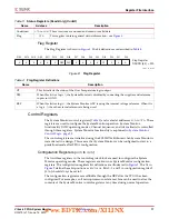
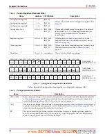
Register File Interface
Channel Sequencer Registers (
48h
to
4Fh
)
These registers are used to program the channel sequencer functionality (see
).
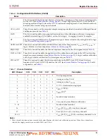
Alarm Registers (
50h
to
57h
)
These registers are used to program the alarm thresholds for the automatic alarms on the
internally monitored channels, temperature, V
CCINT
, and V
CCAUX
DRP JTAG Interface
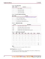
System Monitor uses a full JTAG interface extension to the System Monitor DRP interface.
This allows Read/Write access to the System Monitor DRP through the existing on-chip
JTAG infrastructure. No instantiation is required to access the System Monitor DRP
interface over JTAG. A Boundary-Scan instruction (10-bit instruction =
1111110111
)
called SYSMON has been added to Virtex-6 devices to allow access to the System Monitor
DRP through the JTAG TAP. All System Monitor JTAG instructions are 32-bits in length.
For more information on the Virtex-6 FPGA Boundary-Scan instructions and usage, see the
Virtex-6 FPGA Configuration Guide
. Read and Write operations using the System Monitor
JTAG DRP interface are described in the next sections. Users unfamiliar with basic JTAG
functionality should understand the JTAG standard (IEEE1149.1) before proceeding.
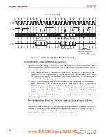
System Monitor DRP JTAG Write Operation
shows a timing diagram for a Write operation to the SYSMON DRP through the
JTAG TAP. The DRP is accessed through the System Monitor Data register (SYSMON DR).
Before the SYSMON DR is accessed, the instruction register (IR) must first be loaded with
the SYSMON instruction. The Controller is first placed in the IR-scan mode, and the
SYSMON instruction is shifted to the IR.
After the SYSMON instruction is loaded, all data register (DR)-scan operations are carried
out on the SYSMON DR. When the data shifted into SYSMON DR is a JTAG DRP Write
command, the SYSMON DRP arbitrator carries out a DRP write. The format of this Write
command is described in
. The SYSMON DR contents are
transferred to the SYSMON DRP arbitrator (see
) during the
Update-DR state. After the Update-DR state, the arbitrator manages the new data transfer
to the System Monitor DRP register. This takes up to six DRP Clock (DCLK) cycles if a DRP
access from the fabric is already in progress.
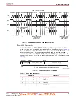
During the Capture-DR phase (just before data is shifted into the SYSMON DR), DRP data
is captured from the arbitrator. Depending on the last JTAG DRP command, this data could
be old data, previously written to the DRP or requested new Read data (see
Monitor JTAG DRP Read Operation, page 22
). This captured data is shifted out (LSB first)
on DO as the new JTAG DRP command is shifted in. The 16 LSBs of this 32-bit word
contain the JTAG DRP data. The 16 MSBs are set to zero.
If multiple writes to the SYSMON DR are taking place, it might be necessary to idle the
TAP Controller for several TCK cycles before advancing to the next write operation. This is
illustrated in
. The idle cycles allow the arbitrator to complete the Write operation
to the System Monitor DRP register. If DCLK is running approximately 6 x TCK, these idle
states are not necessary. However, inserting ten or so idle states ensures all transfers are
inherently safe.
www.BDTIC.com/XILINX


