background image

Virtex-7 FPGA VC7222 

Characterization Kit IBERT

Getting Started Guide

UG971 (Vivado Design Suite v2015.1) April 27, 2015

Summary of Contents for Virtex-7 FPGA VC7222 IBERT

Page 1: ...Virtex 7 FPGA VC7222 Characterization Kit IBERT Getting Started Guide UG971 Vivado Design Suite v2015 1 April 27 2015...

Page 2: ...e GTH IBERT Demonstration page 9 and Running the GTZ IBERT Demonstration page 28 sections and In Case of RX Bit Errors was added to both sections 06 12 2014 5 0 Updated for Vivado Design Suite 2014 2...

Page 3: ...Vivado Design Suite 2015 1 The ZIP project file name changed to rdf0297 vc7222 ibert 2015 1 zip Updated Figure 1 4 Figure 1 10 Figure 1 15 Figure 1 18 Figure 1 29 Figure 1 31 Figure 1 32 Figure 2 1 F...

Page 4: ...Board for GTH and GTZ IBERT Testing 7 Extracting the Project Files 7 Running the GTH IBERT Demonstration 9 Running the GTZ IBERT Demonstration 28 SuperClock 2 Frequency Table 43 Chapter 2 Creating the...

Page 5: ...in Virtex 7 FPGA VC7222 GTH and GTZ Transceiver Characterization Board User Guide UG965 Ref 1 The IBERT GTH demonstration operates one GTH Quad at a time The procedure consists of 1 Setting Up the VC...

Page 6: ...demonstration designs One Samtec BullsEye cable One skew matched reference clock cable set Eight SMA female to female F F adapters Six 50 SMA terminators GTH transceiver power supply module installed...

Page 7: ...f 1 2 Install the GTH and GTZ transceiver power modules into connectors J29 J102 and J5 and J71 respectively 3 Install the SuperClock 2 module a Align the three metal standoffs on the bottom side of t...

Page 8: ...c7222_ibert_q114_debug_nets ltx vc7222_ibert_q115_debug_nets ltx vc7222_ibert_q213_debug_nets ltx vc7222_ibert_q214_debug_nets ltx vc7222_ibert_q215_debug_nets ltx vc7222_ibert_q300_debug_nets ltx Tcl...

Page 9: ...he files to a working directory on the host computer Running the GTH IBERT Demonstration The GTH IBERT demonstration operates one GTH Quad at a time This section describes how to test GTH Quad 115 whi...

Page 10: ...and might not reflect the current revision of the board All GTH transceiver pins and reference clock pins are routed from the FPGA to a connector pad which interfaces with the Samtec BullsEye connecto...

Page 11: ...labeled CLKOUT provide LVDS clock outputs from the Si5368 clock multiplier jitter attenuator device on the clock module The SMA pair labeled Si570_CLK provides LVDS clock output from the Si570 progra...

Page 12: ...g the BullsEye cable assembly to the board firmly secure the blue elastomer seal provided with the cable assembly to the bottom of the connector housing if it is not already inserted see Figure 1 4 No...

Page 13: ...Transceiver Clock Connections See Figure 1 2 to identify the P and N coax cables connected to the CLK0 reference clock inputs Connect these cables to the SuperClock 2 module as follows CLK0_P coax ca...

Page 14: ...mit and receive cables as shown in Figure 1 7 and detailed in the following list TX0_P SMA F F Adapter RX0_P TX0_N SMA F F Adapter RX0_N TX1_P SMA F F Adapter RX1_P TX1_N SMA F F Adapter RX1_N TX2_P S...

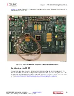
Page 15: ...Configuring the FPGA This section describes how to configure the FPGA using the SD card included with the board The FPGA can also be configured through Vivado Design Suite using the bit files availabl...

Page 16: ...FPGA A switch is in the ON position if set to the far right and in the OFF position if set to the far left For the Quad 115 GTH IBERT demonstration set ADR2 ON ADR1 OFF and ADR0 ON The MODE bit switch...

Page 17: ...15 Chapter 1 VC7222 IBERT Getting Started Guide Setting Up the Vivado Design Suite 1 Start Vivado Design Suite on the host computer and click Flow Open Hardware Manager highlighted in Figure 1 10 X Re...

Page 18: ...ager window click Open New Target highlighted in Figure 1 11 3 An Open Hardware Target wizard starts Click Next to run the wizard 4 In the Hardware Server Settings window select Local server target is...

Page 19: ...rdware Targets and the JTAG chain contents of the selected cable appear under Hardware Devices Figure 1 12 Select the xilinx_tcf target and keep the JTAG Clock Frequency at the default value 15 MHz Cl...

Page 20: ...l oscillator Si5368 jitter attenuating clock multiplier Outputs from either source can be used to drive the transceiver reference clocks To start the SuperClock 2 module 1 The Vivado Design Suite Hard...

Page 21: ...etting Started Guide 2 In the Hardware window right click XC7VH580T_1 and select Refresh Device Figure 1 14 Note If the FPGA was not programmed using the SD card provide both the programming and the p...

Page 22: ...Suite reports that the XC7VH580T is programmed and displays the SuperClock 2 VIO core and the IBERT core To configure the SuperClock 2 module click Tools Run Tcl Script Figure 1 15 In the Run Script w...

Page 23: ...uencies ROM addresses and start signals are selected Figure 1 16 Note The ROM address values for the Si5368 and Si570 devices i e Si5368 ROM Addr and Si570 ROM Addr are preset to 3 to produce an outpu...

Page 24: ...ick Layout Serial I O Analyzer From the top of the Hardware Manager window select Auto Detect Links to display all available links automatically Links can also be created manually in the Links window...

Page 25: ...ed The options in this window are used to link any TX GT to any RX GT To create links select the TX GT and RX GT from the two lists then click the Add Link button For this project connect the followin...

Page 26: ...erClock 2 Module the IBERT demonstration is configured and running The status and test settings are displayed on the Links tab in the Links window shown in Figure 1 19 Note the line rate and the error...

Page 27: ...onnected and flush on the board Increase the TX differential swing of the transceiver to compensate for any loss due to PCB process variation Click the respective TX Reset button followed by BERT Rese...

Page 28: ...e The VC7222 board ships with one BullsEye cable while the provided example uses two cables and activates all 8 GTZ lanes In the absence of a second BullsEye cable only one of the GTZ quads Q300A or Q...

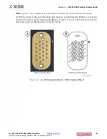
Page 29: ...gure 1 21 A shows the connector pad and Figure 1 21 B and C show the connectors pinout The SuperClock 2 module provides LVDS clock outputs for the GTH and the GTZ transceivers reference clock in the I...

Page 30: ...he Samtec BullsEye connector to either GTZ Quad Q300A or Q300B Figure 1 22 aligning the two indexing pins on the bottom of the connector with the guide holes on the board Hold the connector flush with...

Page 31: ...igure 1 23 J56 REFCLK0_P SMA connector J7 CLKOUT2_P on the SuperClock 2 module J57 REFCLK0_N SMA connector J8 CLKOUT2_N on the SuperClock 2 module Note Any one of the five differential outputs from th...

Page 32: ...he following list TX0_P SMA F F Adapter RX0_P TX0_N SMA F F Adapter RX0_N TX1_P SMA F F Adapter RX1_P TX1_N SMA F F Adapter RX1_N TX2_P SMA F F Adapter RX2_P TX2_N SMA F F Adapter RX2_N TX3_P SMA F F...

Page 33: ...section describes how to configure the FPGA using the SD card included with the Virtex 7 FPGA VC7222 GTH and GTZ Transceiver Characterization Board The FPGA can also be configured through Vivado Desig...

Page 34: ...ter and the Micro B plug connects to U57 the Digilent USB JTAG configuration port on the VC7222 board 4 Select the GTZ IBERT demonstration with the System ACE SD Controller SYSACE 2 CFG switch SW8 The...

Page 35: ...Suite The procedure to launch the Vivado Suite is detailed in Setting Up the Vivado Design Suite page 17 In the Open Hardware Target window it is highly recommended to lower the JTAG clock frequency...

Page 36: ...cillator An Si5368 jitter attenuating clock multiplier Outputs from either source can be used to drive the transceiver reference clocks To start the SuperClock 2 module 1 The Vivado Design Suite Hardw...

Page 37: ...etting Started Guide 2 In the Hardware window right click XC7VH580T_1 and select Refresh Device Figure 1 28 Note If the FPGA was not programmed using the SD card provide both the programming and the p...

Page 38: ...Suite reports that the XC7VH580T is programmed and displays the SuperClock 2 VIO core and the IBERT core To configure the SuperClock 2 module click Tools Run Tcl Script Figure 1 29 In the Run Script w...

Page 39: ...uencies ROM addresses and start signals are selected Figure 1 30 Note The ROM address values for the Si5368 and Si570 devices i e Si5368 ROM Addr and Si570 ROM Addr are preset to 81 to produce an outp...

Page 40: ...ick Layout Serial I O Analyzer From the top of the Hardware Manager window select Auto Detect Links to display all available links automatically Links can also be created manually in the Links window...

Page 41: ...w are used to link any TX GT to any RX GT To create links select the TX GT and RX GT from the two lists then click the Add Link button For this project connect the following links Figure 1 32 Lane0 TX...

Page 42: ...s see the Status Column in Figure 1 33 Verify that there are no bit errors Note External or internal CTLE tuning might be required for successful GTZ operation If the Link Status shows No Link for on...

Page 43: ...tion SuperClock 2 Frequency Table Table 1 2 lists the addresses for the frequencies that are programmed into the SuperClock 2 read only memory ROM Table 1 2 Si570 and Si5368 Frequency Table Address Pr...

Page 44: ...063 86 Generic 280 27 Interlaken 531 25 57 SMPTE435M 334 125 87 Generic 285 28 OBSAI 76 8 58 SMPTE435M 668 25 88 Generic 290 29 OBSAI 153 6 59 XAUI 78 125 89 Generic 295 90 Generic 300 103 Generic 36...

Page 45: ...roller The procedure assumes Quad 115 and 13 0 Gb s line rate but cores for any of the GTH Quads with any supported line rate can be created following the same series of steps For more details on gene...

Page 46: ...omized IP Location dialog window opens not shown click Next 4 In the Manage IP Settings window select a part by clicking the button next to the Part field A Select Device window pops up Use the drop d...

Page 47: ...5 In the Manage IP Settings window select Verilog for Target language Vivado Simulator for Target simulator Mixed for Simulator language and a directory to save the customized IP Figure 2 3 Click Fin...

Page 48: ...Suite v2015 1 April 27 2015 Chapter 2 Creating the GTH IBERT Core 6 In the IP Catalog window open the Debug Verification folder then open the Debug folder and double click IBERT 7 Series GTH Figure 2...

Page 49: ...2 Creating the GTH IBERT Core 7 A Customize IP window opens In the Protocol Definition tab change LineRate Gbps to 13 0 Use the drop down menu to change the Refclk MHz to 325 00 Do not change other de...

Page 50: ...v2015 1 April 27 2015 Chapter 2 Creating the GTH IBERT Core 8 In the Protocol Selection tab use the Protocol Selected drop down menu next to QUAD_115 to select Custom 1 13 0 Gbps Figure 2 6 X Ref Targ...

Page 51: ...tab select DIFF SSTL15 for the I O Standard enter AL24 for P Package Pin and AL25 for N Package Pin the FPGA pins that the system clock connects to and ensure the Frequency is set to 200 00 Figure 2...

Page 52: ...the GTH IBERT Core 10 In the Manage IP window Figure 2 3 in the Sources window right click the IBERT IP and select Open IP Example Design Figure 2 8 Specify a location to save the design press OK and...

Page 53: ...11 In the new window select Tools Run Tcl Script In the Run Script window navigate to add_scm2 tcl in the extracted files and press OK The SuperClock 2 Module Design Sources and Constraints are automa...

Page 54: ...ample IBERT wrapper In the Sources window double click example_ibert_7series_gth_0 in the Design Sources folder to open the verilog code Add the top level ports from top_scm2 v to the module declarati...

Page 55: ...15 1 April 27 2015 Chapter 2 Creating the GTH IBERT Core 13 In the Sources window Design Sources should now reflect that the SuperClock 2 module is part of the example IBERT design Figure 2 11 X Ref T...

Page 56: ...14 Click Run Synthesis in the Flow Navigator to synthesize the design Figure 2 12 15 When synthesis is done a Synthesis Complete window pops up Select Open Synthesized Design and click OK Figure 2 13...

Page 57: ...g Core Options tab in the Cell Properties window Change C_USER_SCAN_CHAIN to 3 Figure 2 14 Click File Save Constraints 17 In the Project Manager under Program and Debug click Generate Bitstream Figure...

Page 58: ...e 18 When the Bitstream Generation Completed dialog window appears click Cancel Figure 2 16 19 The generated bitstream is located in the following directory ibert_7series_gtz_0 ibert_7series_gtz_0_exa...

Page 59: ...to create the GTZ IBERT core with integrated SuperClock 2 controller Vivado Design Suite 2015 1 is required to rebuild the design shown here For more details on generating IBERT cores see the Vivado...

Page 60: ...5 Chapter 3 Creating the GTZ IBERT Core 1 In the IP Catalog window expand the Debug Verification folder then expand the Debug folder Double click or right click the IBERT 7 Series GTZ to run the GTZ c...

Page 61: ...3 Creating the GTZ IBERT Core 2 A Customize IP window opens In the Design Options tab set the system clock frequency to 200 MHz the input Standard to LVDS the P and N Pin location to AL24 and AL25 re...

Page 62: ...the Line Rate to 28 05 Gbps and the reference frequency to 255 MHz Figure 3 3 Note The reference frequency can be set to any of the available options in the drop down menu The same frequency should be...

Page 63: ...T Core In the Lane Selection tab select Protocol0 28 05 from the drop down menu Figure 3 4 Review the summary and press OK to finish the IP customization A Generate Output Products window opens Leave...

Page 64: ...g the GTZ IBERT Core 4 Back in the Manage IP window from the Sources window right click the IBERT IP and select Open IP Example Design Figure 3 5 Specify a location to save the design press OK and the...

Page 65: ...esign Sources and Constraints are added to the example design Figure 3 6 6 The SuperClock 2 source code now needs to be added to the example IBERT wrapper Double click ibert_7series_gtz_0_example in t...

Page 66: ...g Started Guide www xilinx com 66 UG971 Vivado Design Suite v2015 1 April 27 2015 Chapter 3 Creating the GTZ IBERT Core X Ref Target Figure 3 7 Figure 3 7 SuperClock 2 in the Example IBERT Wrapper 8 B...

Page 67: ...2015 1 April 27 2015 Chapter 3 Creating the GTZ IBERT Core 7 In the Sources window Design Sources should now reflect that the SuperClock 2 module is part of the example IBERT design Figure 3 8 X Ref T...

Page 68: ...ick Run Synthesis in the Flow Navigator which synthesizes the complete design Figure 3 9 9 When synthesis is done a Synthesis Complete window pops up Select Open Synthesized Design and click OK Figure...

Page 69: ...Debug Core Options tab in the Cell Properties window and change the C_USER_SCAN_CHAIN option to 3 Figure 3 11 Click File Save Constraints 11 In the Project Manager window under Program and Debug clic...

Page 70: ...e 12 When the Bitstream Generation Completed dialog window appears click Cancel Figure 3 13 13 The generated bitstream is located in the following directory ibert_7series_gtz_0 ibert_7series_gtz_0_exa...

Page 71: ...ycle Topics include design assistance advisories and troubleshooting tips References The most up to date information related to the VC7222 kit and its documentation is available on these websites Virt...

Page 72: ...al loss or damage including loss of data profits goodwill or any type of loss or damage suffered as a result of any action brought by a third party even if such damage or loss was reasonably foreseeab...

Page 73: ...error neglect or default of Customer For any breach by Xilinx of this limited warranty the exclusive remedy of Customer and the sole liability of Xilinx shall be at the option of Xilinx to replace or...

Page 74: ...0 5TQG144I XC3S4000 4FGG900I XC4VFX20 10FFG672C XC5VLX20T 1FFG323C XC95144XL 7TQ144I XCZU19EG 1FFVB1517E XCKU115 2FLVA1517E EK U1 KCU116 G XCZU4EV 1SFVC784E XCZU4EV 1SFVC784I A U200 A64G PQ G XC7S75 2...

Reviews: