background image

ZC706 Evaluation Board User Guide

www.xilinx.com

84

UG954 (v1.5) September 10, 2015

Feature Descriptions

The ZC706 evaluation board supports both the internal XC7Z045 AP SoC sensor 

measurements and the external measurement capabilities of the XADC. Internal 

measurements of the die temperature, VCCINT, VCCAUX, and VCCBRAM are available.

Jumper J52 can be used to select either an external voltage reference (VREF) or on-chip 

voltage reference for the analog-to-digital converter.

For external measurements an XADC header (J63) is provided. This header can be used to 

provide analog inputs to the XC7Z045 AP SoC's dedicated VP/VN channel, and to the 

VAUXP[0]/VAUXN[0], VAUXP[8]/VAUXN[8] auxiliary analog input channels. Simultaneous 

sampling of Channel 0 and Channel 8 is supported.

A user-provided analog signal multiplexer card can be used to sample additional external 

analog inputs using the 4 GPIO pins available on the XADC header as multiplexer address 

lines. 

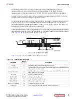
Figure 1-38

 shows the XADC header connections.

Table 1-39

 describes the XADC header J40 pin functions.

X-Ref Target - Figure 1-38

Figure 1-38:

XADC Header (J63)

UG954_c1_38_041113

XADC_VP

XADC_VAUX0N

XADC_VAUX8P

XADC_DXN

XADC_VCC_HEADER

XADC_VN
XADC_VAUX0P

XADC_VAUX8N
XADC_DXP
XADC_VREF

XADC_GPIO_0
XADC_GPIO_2

XADC_GPIO_1
XADC_GPIO_3

J63

1
3
5
7
9

11
13
15
17
19

2
4
6
8
10
12
14
16
18
20

GND

XADC_AGND

XADC_AGND

XADC_VCC5V0

VCC1V5_PL

Table 1-39:

XADC Header J63 Pinout

Net Name

J63 Pin

Number

Description

VN, VP

1, 2

Dedicated analog input channel for the XADC.

XADC_VAUX0P, N

3, 6

Auxiliary analog input channel 0. Also supports use as I/O inputs when anti 

alias capacitor is not present.

XADC_VAUX8N, P

7, 8

Auxiliary analog input channel 8. Also supports use as I/O inputs when anti 

alias capacitor is not present.

DXP, DXN

9, 12

Access to thermal diode.

XADC_AGND

4, 5, 10

Analog ground reference.

XADC_VREF

11

1.25V reference from the board.

XADC_VCC5V0

13

Filtered 5V supply from board.

XADC_VCC_HEADER

14

Analog 1.8V supply for XADC.

VCC1V5_PL

15

VCCO supply for bank which is the source of DIO pins.

Send Feedback

Summary of Contents for ZC706

Page 1: ...ZC706 Evaluation Board for the Zynq 7000 XC7Z045 All Programmable SoC User Guide UG954 v1 5 September 10 2015...

Page 2: ...ing fail safe performance you assume sole risk and liability for use of Xilinx products in such critical applications please refer to Xilinx s Terms of Sale which can be viewed at www xilinx com legal...

Page 3: ...In Table 1 33 J5 pin H22 changed to XC7Z045 U1 pin AH26 and H23 changed to AH27 The section ZC706 Board Power System page 72 was added Voltage levels were changed in VADJ Voltage Control page 79 Table...

Page 4: ...ble Logic JTAG Programming Options 31 Programmable Logic JTAG Select Switch 31 FMC Connector JTAG Bypass 33 Clock Generation 33 System Clock 34 Programmable User Clock 35 User SMA Clock Source 36 Proc...

Page 5: ...e Control 80 Monitoring Voltage and Current 80 Cooling Fan 82 XADC Analog to Digital Converter 83 Appendix A Default Switch and Jumper Settings Switches 86 Jumpers 87 Appendix B VITA 57 1 FMC Connecto...

Page 6: ...ZC706 Evaluation Board User Guide www xilinx com 6 UG954 v1 5 September 10 2015 Standards 114 Electromagnetic Compatibility 115 Safety 115 Markings 115 Send Feedback...

Page 7: ...t HPC FMC connectors ZC706 Evaluation Board Features The ZC706 evaluation board features are listed in here Detailed information for each feature is provided in Feature Descriptions starting on page 1...

Page 8: ...Express endpoint connectivity Gen1 4 lane x4 Gen2 4 lane x4 SFP Connector Ethernet PHY RGMII interface with RJ 45 connector USB to UART bridge with mini B USB connector HDMI codec with HDMI connector...

Page 9: ...ushbuttons SRST_B PS reset button POR_B PS reset button VITA 57 1 FMC HPC connector VITA 57 1 FMC LPC connector Power on off slide switch Program_B pushbutton Power management with PMBus voltage and c...

Page 10: ...igure 1 1 ZC706 Evaluation Board Block Diagram U1 Zync 7000 AP SoC XC7Z045 2FFG900C Processing System Programmable Logic UG954_c1_01_1002012 JTAG Module and JTAG Header Page 16 Dual Quad SPI Flash Mem...

Page 11: ...381513 Page Number 1 Zynq 7000 XC7Z045 AP SoC page 14 Zynq 7000 All Programmable SoC with fan sink XC7Z045T 2FFG900C with Radian INC3001 7_1 5BU_LI98 fan sink 2 DDR3 SODIMM Memory PL page 18 DDR3 SODI...

Page 12: ...ri Speed Ethernet PHY PL page 47 RGMII only 10 100 1000 Mb s Ethernet PHY w RJ45 U51 P3 Marvell 88E1116RA0 NNC1C000 29 16 GTX Differential SMA TX and RX P N J35 J34and J32 J33 Rosenberger 32K10K 400L5...

Page 13: ...nnector J5 Samtec ASP_134603_01 28 32 Power Management page 77 Power Management System top and bottom of board TI UCD90120ARGC in conjunction w various regulators 48 57 33 XADC Analog to Digital Conve...

Page 14: ...diagram is shown in Figure 1 3 The PS integrates two ARM Cortex A9 MPCore application processors AMBA interconnect internal memories external memory interfaces and peripherals including USB Ethernet S...

Page 15: ...1 4 Zynq 7000 Block Diagram 2x USB 2x GigE 2x SD Zynq 7000 AP SoC I O Peripherals IRQ IRQ EMIO SelectIO Resources DMA 8 Channel CoreSight Components Programmable Logic DAP DevC SWDT DMA Sync Notes 1...

Page 16: ...nual UG585 Encryption Key Backup Circuit The XC7Z045 AP SoC U1 implements bitstream encryption key technology The ZC706 board provides the encryption key backup battery circuit shown in Figure 1 5 The...

Page 17: ...B2 Lithium Battery Seiko TS518SE_FL35E 1 5V 2 1 3 BAS40 04 D7 40V 200 mW NC FPGA_VBATT VCCAUX R9 4 70K 1 1 16W To XC7Z045 AP SoC U1 Pin P9 VCCBATT Table 1 3 I O Voltage Rails XC7Z045 U1 Bank Net Name...

Page 18: ...y interface connected to these banks that requires the VTTREF voltage must use this FPGA voltage reference The connections between the DDR3 memory and the AP SoC are listed in Table 1 4 PS Bank 500 VC...

Page 19: ...R3_D6 SSTL15 16 DQ6 K6 PL_DDR3_D7 SSTL15 18 DQ7 G6 PL_DDR3_D8 SSTL15 21 DQ8 H4 PL_DDR3_D9 SSTL15 23 DQ9 H6 PL_DDR3_D10 SSTL15 33 DQ10 H3 PL_DDR3_D11 SSTL15 35 DQ11 G1 PL_DDR3_D12 SSTL15 22 DQ12 H2 PL_...

Page 20: ...L15 149 DQ41 F13 PL_DDR3_D42 SSTL15 157 DQ42 G16 PL_DDR3_D43 SSTL15 159 DQ43 G15 PL_DDR3_D44 SSTL15 146 DQ44 E12 PL_DDR3_D45 SSTL15 148 DQ45 D13 PL_DDR3_D46 SSTL15 158 DQ46 E13 PL_DDR3_D47 SSTL15 160...

Page 21: ...QS2_P DIFF_SSTL15 47 DQS2_P A4 PL_DDR3_DQS3_N DIFF_SSTL15 62 DQS3_N A5 PL_DDR3_DQS3_P DIFF_SSTL15 64 DQS3_P K8 PL_DDR3_DQS4_N DIFF_SSTL15 135 DQS4_N L8 PL_DDR3_DQS4_P DIFF_SSTL15 137 DQS4_P F12 PL_DDR...

Page 22: ...tions between the DDR3 component memory and XC7Z045 AP SoC bank 502 are listed in Table 1 5 E7 PL_DDR3_CAS_B SSTL15 115 CAS_B H11 PL_DDR3_RAS_B SSTL15 110 RAS_B D10 PL_DDR3_CKE0 SSTL15 73 CKE0 C7 PL_D...

Page 23: ...26 C2 DQ26 U5 J29 PS_DDR3_DQ27 C8 DQ27 U5 K30 PS_DDR3_DQ28 E3 DQ28 U5 M29 PS_DDR3_DQ29 E8 DQ29 U5 L30 PS_DDR3_DQ30 D2 DQ30 U5 M30 PS_DDR3_DQ31 E7 DQ31 U5 C27 PS_DDR3_DM0 B7 DM0 U2 C26 PS_DDR3_DQS0_P C...

Page 24: ...23 PS_DDR3_A9 M3 A9 U2 U3 U4 U5 G26 PS_DDR3_A10 H7 A10 U2 U3 U4 U5 H24 PS_DDR3_A11 M7 A11 U2 U3 U4 U5 K23 PS_DDR3_A12 K7 A12 U2 U3 U4 U5 H23 PS_DDR3_A13 N3 A13 U2 U3 U4 U5 J24 PS_DDR3_A14 N7 A14 U2 U3...

Page 25: ...the connections of the linear Quad SPI flash memory on the ZC706 evaluation board For more details see the Spansion S25FL128SAGMFIR01 data sheet Ref 16 Table 1 6 Quad SPI Flash Memory Connections to...

Page 26: ...QSPI1_IO2 NC NC NC NC NC NC NC 1 2 3 4 5 6 7 8 SO16_50P300X413 U58 GND S25FL128SAGMFIR01 DQ3_HOLD_B VCC NC0 NC1 NC2 NC3 S_B DQ1 C DQ0 NC7 NC6 NC5 NC4 VSS DQ2_VPP_WP_B 16 15 14 13 12 11 10 9 NC NC NC...

Page 27: ...USB3320 is clocked by a 24 MHz crystal Consult the SMSC USB3320 data sheet for clocking mode details Ref 17 The interface to the USB3320 transceiver is implemented through the IP in the XC7Z045 AP So...

Page 28: ...Name Description USB3320 U12 Pin Pin Name 1 VBUS USB_VBUS_SEL 5V from host system 22 2 D_N USB_D_N Bidirectional differential serial data N side 19 3 D_P USB_D_P Bidirectional differential serial dat...

Page 29: ...TA7_13 DATA1_4 SPK_L_15 REFCLK_26 SPK_R_16 XO_25 VDD18_30 DATA3_6 STP_29 VDD18_28 RESETB_27 CTR_GND_33 SHLD5 SHLD6 GND SHLD4 VBUS D_N D_P SHLD1 SHLD2 SHLD3 ID 1 2 DEVICE MODE OFF DEVICE MODE 2 3 HOST...

Page 30: ...5 VCCP1V8 18 13 14 15 2 3 5 6 7 8 9 1 10 4 11 12 16 17 J30 67840 8001 22 SDIO_CLK VCC3V3_PS 1 2 C41 0 1 F 25V X5R SDIO_DAT2 22 SDIO_DAT0 22 22 SDIO_DAT1 SDIO_CD_DAT3 22 22 SDIO_CMD Table 1 10 SDIO Con...

Page 31: ...e through a 3 to 1 analog switch U45 U46 and U47 controlled by a 2 position DIP switch at SW4 Figure 1 10 shows the JTAG analog switches and DIP switch SW4 X Ref Target Figure 1 9 Figure 1 9 JTAG Chai...

Page 32: ...log switch settings are shown in Table 1 11 X Ref Target Figure 1 10 Figure 1 10 PL JTAG Programming Source Analog Switch UG954_c1_10_041113 SDA02H1SBD SW4 VCC3V3 4 3 JTAG_SEL_1 JTAG_SEL_2 R20 4 7k 0...

Page 33: ...e AP SoC U1 The JTAG connectivity on the ZC706 board allows a host computer to download bitstreams to the AP SoC using the Xilinx iMPACT software In addition the JTAG connector allows debug tools such...

Page 34: ...ator SiTime See Processing System Clock Source page 37 GTX SMA REF Clock J36 P J31 N User clock input SMAs See GTX SMA Clock SMA_MGT_REFCLK_P and SMA_MGT_REFCLK_N page 37 Jitter Attenuated Clock U60 S...

Page 35: ...rd has a programmable low jitter 3 3V LVDS differential oscillator U37 connected to the MRCC inputs of bank 10 This USRCLK_P and USRCLK_N clock signal pair is connected to XC7Z045 AP SoC U1 pins AF14...

Page 36: ...LOCK_N connected to U1 pin AD19 Bank 9 Vcco is VADJ_FPGA a variable voltage 1 8V 2 5V 3 3V depending on the ZC706 FMC interface banks voltage The USER_SMA_CLOCK input voltage swing should not exceed t...

Page 37: ...e SiT8103 data sheet Ref 20 GTX SMA Clock SMA_MGT_REFCLK_P and SMA_MGT_REFCLK_N Figure 1 2 callout 10 The ZC706 board includes a pair of SMA connectors for a GTX clock wired to GTX Quad bank 111 This...

Page 38: ...ter attenuated clock Si5324_OUT_C_P Si5324_OUT_C_N is then routed as a reference clock to GTX Quad 110 inputs MGTREFCLK1P AP SoC U1 pin AC8 and MGTREFCLK1N AP SoC U1 pin AC7 The primary purpose of thi...

Page 39: ...6 Jitter Attenuated Clock UG954_c1_16_041113 R89 4 7 K 5 SI5324_VCC Si5324C C GM Clock Multiplier Jitter Attenuator VDD3 GND XB XA NC5 32 6 30 29 28 U60 CKOUT1_N 7 33 CKOUT1_P C137 0 1 F 25V X5R C136...

Page 40: ...nsceivers allocated to FMC_HPC_DP 3 0 _C2M_P N Quad 110 MGTREFCLK0 FMC_HPC_GBTCLK1_M2C clock MGTREFCLK1 SI5324_OUT_C_P N jitter attenuator clock Contains 4 GTX transceivers allocated to FMC_HPC_DP 7 4...

Page 41: ...GTPRXP0_109 FMC_HPC_DP0_M2C_P C6 AH9 MGTPRXN0_109 FMC_HPC_DP0_M2C_N C7 AK6 MGTPTXP1_109 FMC_HPC_DP1_C2M_P A22 AK5 MGTPTXN1_109 FMC_HPC_DP1_C2M_N A23 AJ8 MGTPRXP1_109 FMC_HPC_DP1_M2C_P A2 AJ7 MGTPRXN1_...

Page 42: ..._110 FMC_HPC_DP6_M2C_N B17 AD2 MGTPTXP3_110 FMC_HPC_DP7_C2M_P B32 AD1 MGTPTXN3_110 FMC_HPC_DP7_C2M_N B33 AD6 MGTPRXP3_110 FMC_HPC_DP7_M2C_P B12 AD5 MGTPRXN3_110 FMC_HPC_DP7_M2C_N B13 AA8 MGTREFCLK0P_1...

Page 43: ...11 SMA_MGT_TX_P J35 1 GTX TX RX SMA Y1 MGTPTXN1_111 SMA_MGT_TX_N J34 1 AB6 MGTPRXP1_111 SMA_MGT_RX_P 2 J32 1 AB5 MGTPRXN1_111 SMA_MGT_RX_N 2 J33 1 W4 MGTPTXP2_111 SFP_TX_P 18 SFP Conn P2 W3 MGTPTXN2_1...

Page 44: ...dge connector It is AC coupled to the AP SoC through the MGTREFCLK0 pins of Quad 112 PCIE_CLK_Q0_P is connected to AP SoC U1 pin N8 and the _N net is connected to pin N7 The PCI Express clock circuit...

Page 45: ...e PCIe 4 Lane Conn P4 Pin Number GTX_BANK_112 T2 MGTPTXP0_112 PCIE_TX3_P A29 1 T1 MGTPTXN0_112 PCIE_TX3_N A30 1 V6 MGTPRXP0_112 PCIE_RX3_P B27 V5 MGTPRXN0_112 PCIE_RX3_N B28 R4 MGTPTXP1_112 PCIE_TX2_P...

Page 46: ...RD_P RD_N LOS VEET_3 VEET_2 VEER_3 VEER_1 VEER_2 VEET_1 RS0 RS1 MOD_ABS SCL SDA TX_DISABLE TX_FAULT GND11 2 3 LOW BW TX 2 3 LOW BW RX 1 2 FULL BW RX SFP Enable 1 2 FULL BW TX SFP_RS1 SFP_VCCT 32 21 2...

Page 47: ...I mode with PHY address 0b00111 using the settings shown in Table 1 19 These settings can be overwritten via software commands passed over the MDIO interface Table 1 17 AP SoC U1 to SFP Module Connect...

Page 48: ...PHYAD 4 1 CONFIG3 3 GND RGMII_TX 0 RGMII_RX 0 PHY_LED0 RGMII_TX 0 RGMII_RX 1 PHY_LED1 RGMII_TX 1 RGMII_RX 0 VCCP1V8 RGMII_TX 1 RGMII_RX 1 Table 1 20 Ethernet Connections XC7Z045 AP SoC to the PHY Dev...

Page 49: ...ost PC when the USB cable is plugged into the USB port on the ZC706 evaluation board The CP2013GM TX and RX pins are wired to the UART_1 IP block within the XC7Z045 AP SoC PS I O Peripherals set The X...

Page 50: ...vided on a Molex 500254 1927 HDMI type A receptacle at P1 The ADV7511 supports 1080P 60Hz YCbCr 4 4 4 encoding via 24 bit input data mapping The ZC706 evaluation board supports the following HDMI devi...

Page 51: ...27 31 37 75 47 26 76 77 49 19 1 30 U53 ADV7511 HDMI_D10 VADJ HDMI_HEAC_C_N HDMI_AVDD HDMI_PLVDD HDMI_PLVDD 2 1 X5R 25V 0 1 F C88 HDMI_CLK HDMI_HSYNC HDMI_VSYNC HDMI_INT 1 1 1 10W 2 43K R165 R164 2 43...

Page 52: ...DMI_R_D16 LVCMOS25 80 D16 AB26 HDMI_R_D17 LVCMOS25 78 D17 AA28 HDMI_R_D18 LVCMOS25 74 D18 AC26 HDMI_R_D19 LVCMOS25 73 D19 AE30 HDMI_R_D20 LVCMOS25 72 D20 Y25 HDMI_R_D21 LVCMOS25 71 D21 AA29 HDMI_R_D22...

Page 53: ...AIN is routed to level shifter U88 The output side of the two level shifters are wired to the common I2C bus IIC_SDA and _SCL_MAIN which is connected to TI Semiconductor PCA9548 1 to 8 channel I2C bus...

Page 54: ...witch U65 CH6 FMC_LPC_IIC_SDA SCL CH5 FMC_HPC_IIC_SDA SCL CH4 IIC_RTC_SDA SCL CH3 PORT_EXPANDER_SDA SCL CH2 EEPROM_IIC_SDA SCL CH1 IIC_SDA SCL_HDMI CH0 USRCLK_SFP_SDA SCL XC7Z045 AP SoC PS Bank 501 1...

Page 55: ...e clock connections to the XC7Z045 AP SoC and the PCA9548 8 Channel bus switch are listed in Table 1 26 Refer to Table 1 25 for the RTC I2C address Information about the RTC 8564JE is available at the...

Page 56: ...icator DS13 VCC1V5_PL GRN VCC1V5_PL voltage on indicator DS15 VADJ_FPGA GRN VADJ_FPGA voltage on indicator DS16 VCC3V3_FPGA GRN VCC3V3 voltage on indicator DS20 PS_DDR_LINEAR_PG GRN VTTDDR_PS voltage...

Page 57: ...other product information for the Marvell 881116R Alaska Gigabit Ethernet Transceiver Ref 24 User I O Figure 1 2 callout 22 24 The ZC706 evaluation board provides the following user and general purpo...

Page 58: ...45 AP SoC U1 X Ref Target Figure 1 25 Figure 1 25 User LEDs UG954_c1_25_041113 1 3 2 1 2 1 2 Q7 NDS331N 460 mW DS8 VCC3V3 R390 261 0 1W 1 GND 1 3 2 Q8 NDS331N 460 mW DS9 VCC3V3 R391 261 0 1W 1 GND 1 3...

Page 59: ...ttons VADJ GPIO_SW_LEFT R66 4 7 k 0 1 W 5 GND 4 3 2 1 SW7 VADJ GPIO_SW_CENTER R72 4 7 k 0 1 W 5 GND 4 3 2 1 SW9 UG954_c1_26_041113 VADJ GPIO_SW_RIGHT R67 4 7 k 0 1 W 5 GND 4 3 2 1 SW8 VCC1V5_PL PL_CPU...

Page 60: ...V to VADJ level shifter U40 See the Digilent website for information on Digilent Pmod Peripheral Modules Ref 35 Information about the TCA641APWR and TXS0108E devices is available at the Texas Instrume...

Page 61: ...c1_28_031715 R310 DNP DNP DNP R330 0 1 10W 5 R65 4 7 1 10W 5 1 2 1 2 1 2 TXS0108E C105 0 1UF 10V X5R C104 0 1UF 10V X5R J58 1 2 GND 1 2 GND GND PORT_EXPANDER_DDR3_SDA PORT_EXPANDER_DDR3_SCL NC IIC_PMO...

Page 62: ...r switch is SW1 Sliding the switch actuator from the Off to On position applies 12V power from J22 a 6 pin mini fit connector Green LED DS22 illuminates when the ZC706 evaluation board power is on See...

Page 63: ...ering this cable see Ref 36 Figure 1 30 shows the power connector J22 power switch SW1 and indicator LED DS22 Program_B Pushbutton Figure 1 2 callout 28 Switch SW10 grounds the XC7Z045 AP SoC PROG_B p...

Page 64: ...1_31_041113 FPGA_PROG B VCC3V3 R73 4 7 k 0 1 W 5 GND 2 1 3 4 SW10 X Ref Target Figure 1 32 Figure 1 32 PS Power On and System Reset Circuitry UG954_c1_32_041113 MAX16025 Dual Voltage Monitor and Seque...

Page 65: ...ted with 400 pins while the LPC connector is partially populated with 160 pins The connectors are keyed so that a mezzanine card when installed in either of these FMC connectors on the ZC706 evaluatio...

Page 66: ...3 FMC_HPC_DP7_M2C_N 1 AD5 A15 FMC_HPC_DP4_M2C_N 1 AH5 B16 FMC_HPC_DP6_M2C_P 1 AF6 A18 FMC_HPC_DP5_M2C_P 1 AG4 B17 FMC_HPC_DP6_M2C_N 1 AF5 A19 FMC_HPC_DP5_M2C_N 1 AG3 B20 FMC_HPC_GBTCLK1_M2C_P 1 AA8 A2...

Page 67: ...HPC_LA26_N LVCMOS25 T28 C35 VCC12_P N A N A D29 FMC_HPC_TCK_BUF N A U23 15 C37 VCC12_P N A N A D30 FMC_TDI_BUF N A U23 18 C39 VCC3V3 N A N A D31 FMC_HPC_TDO_FMC_LPC_TDI N A U32 2 D32 VCC3V3 N A N A D3...

Page 68: ...C_LA12_N LVCMOS25 AF24 H14 FMC_HPC_LA07_N LVCMOS25 AJ24 G18 FMC_HPC_LA16_P LVCMOS25 AA24 H16 FMC_HPC_LA11_P LVCMOS25 AD23 G19 FMC_HPC_LA16_N LVCMOS25 AB24 H17 FMC_HPC_LA11_N LVCMOS25 AE23 G21 FMC_HPC_...

Page 69: ...NC N A N A J16 NC N A N A K16 NC N A N A J18 NC N A N A K17 NC N A N A J19 NC N A N A K19 NC N A N A J21 NC N A N A K20 NC N A N A J22 NC N A N A K22 NC N A N A J24 NC N A N A K23 NC N A N A J25 NC N...

Page 70: ...2C_P 1 AC4 D5 FMC_LPC_GBTCLK0_M2C_N 1 U7 C7 FMC_LPC_DP0_M2C_N 1 AC3 D8 FMC_LPC_LA01_CC_P LVCMOS25 AF15 C10 FMC_LPC_LA06_P LVCMOS25 AB12 D9 FMC_LPC_LA01_CC_N LVCMOS25 AG15 C11 FMC_LPC_LA06_N LVCMOS25 A...

Page 71: ...A11_P LVCMOS25 AJ16 G19 FMC_LPC_LA16_N LVCMOS25 AE17 H17 FMC_LPC_LA11_N LVCMOS25 AK16 G21 FMC_LPC_LA20_P LVCMOS25 AG26 H19 FMC_LPC_LA15_P LVCMOS25 AB15 G22 FMC_LPC_LA20_N LVCMOS25 AG27 H20 FMC_LPC_LA1...

Page 72: ...n DC DC solution capable of driving up to 20A load The LMZ31520 module can accept an input voltage rail between 3V and 14 5V and deliver an adjustable and highly accurate output voltage as low as 0 6V...

Page 73: ...il 4 VADJ_FPGA VADJ LMZ31506 U86 2 2 5V 6A 54 Addr 101 Rail 5 VCC3V3_FPGA VCC3V3 LMZ31710 U15 4 3 3V 10A Notes ZC706 boards prior to Rev 2 0 implemented different voltage regulators for VCCINT VCCAUX...

Page 74: ...t Sense Voltage Sense Rail Enable PWM Margin Current Sense Voltage Sense I0B I1B I2B I3B S 1 0 YB FMC_ADJ_SEL 1 0 GPIO out FPWM out ADC in ADC in GPIO out FPWM out ADC in ADC in GPIO out FPWM out ADC...

Page 75: ...maximum at the TI UCD90120A ADC input pin when the rail current is at its expected maximum current level as can be seen in the U48 controller power system figure Figure 1 33 The TI UCD90120A module h...

Page 76: ...ed to 0 75V 3 01K 1 00K GND VCC3V3_FPGA_SENSE_P VCC3V3_FPGA_XADC_P VCC3V3_FPGA_SENSE_N VCCINT_XADC_CS_P N VCCAUX_XADC_CS_P N VCC1V5_PL_XADC_P N VCC1V5_PL_XADC_CS_P N VADJ_FPGA_XADC_P N VADJ_FPGA_XADC_...

Page 77: ...e UG933 The ZC706 evaluation board power distribution diagram is shown in Figure 1 35 V VADJ_FPGA NA VADJ_FPGA 2 5V REMOTE SENSE DIVIDED TO DELIVER 0 625V ON VADJ_FPGA_XADC_P VADJ_FPGA_XADC_P 23 S5A 1...

Page 78: ...UX 1 8V 3A U95 p 57 Linear Regulator VCC2V5 2 5V 1 5A U19 p 57 Linear Regulator MGTAVCC 1 0V 3A U93 p 57 Linear Regulator MGTAVTT 1 2V 3A U94 p 57 Linear Regulator VCCAUX_IO 2 0V 3A U92 p 57 Source Si...

Page 79: ...tput U105 2 5A 0 8V 10V Adj Switching Regulator VCCP1V8 1 80V 55 2 5A 0 8V 10V Adj Switching Regulator VCC3V3_PS 3 30V 55 TPS51200DR U27 3A Push Pull Tracking Regulator VTTDDR_PS 0 75V 56 TPS51200DR U...

Page 80: ...r IIC_PORT_EXPANDER SDA SCL bus is wired to the PCA9548ARGER I2C U65 bus switch see I2C Bus page 53 Documentation describing PMBUS programming for the UCD90120A power controller is available at the we...

Page 81: ...0A U48 IMPORTANT In Table 1 37 the values defined in the Shutdown columns are the voltage and current thresholds that cause the regulator to shut down if the value is exceeded The ZC706 power system r...

Page 82: ...7Z045 AP SoC U1 pins AB19 and Table 1 38 Power Rail Sequence On Dependencies for UCD90120A PMBus Controller at Address 101 Device Address Rail Nominal Voltage Turn On Order Turn On Timing UCD90120A 10...

Page 83: ...Bit 1 MSPS Analog to Digital Converter User Guide UG480 for details on the capabilities of the analog front end Figure 1 37 shows the XADC block diagram X Ref Target Figure 1 37 Figure 1 37 XADC Block...

Page 84: ...ltiplexer address lines Figure 1 38 shows the XADC header connections Table 1 39 describes the XADC header J40 pin functions X Ref Target Figure 1 38 Figure 1 38 XADC Header J63 UG954_c1_38_041113 XAD...

Page 85: ...tal Ground board Reference XADC_GPIO_3 2 1 0 19 20 17 18 Digital I O These pins should come from the same bank These IOs should not be shared with other functions because they are required to support...

Page 86: ...er headers called out in Table A 2 are shown in Figure A 1 Table A 1 Default Switch Settings Switch Function Default Selects Figure 1 2 Callout SW1 Board main power On Off Slide Switch OFF Delivered i...

Page 87: ...ET Header OPEN U12 not held in RESET 31 7 J12 U38 REF3012 VREF XADC_AGND to GND L3 inductor bypass OPEN L3 not bypassed 35 8 J13 U38 REF3012 VREF XADC_AGND to GND Select Header 1 2 XADC_AGND connected...

Page 88: ...rnet PHY CONFIG3 pin 3 LED1 or LED0 Select Header OPEN No connection to LED0 or LED1 J45 sets U51 pin 3 CONFIG3 condition 29 26 J48 U12 USB3320 2 0 MODE Select Header 2 3 HOST OTG Mode selected 31 27...

Page 89: ...linx com 89 UG954 v1 5 September 10 2015 Jumpers X Ref Target Figure A 1 Figure A 1 ZC706 Jumper Header Locations UG954_aA_01_042415 34 33 11 24 25 23 4 13 32 7 1 8 31 9 30 10 15 12 14 5 26 28 6 29 27...

Page 90: ...D GA0 12P0V GND 12P0V GND 3P3V GND PG_C2M GND GND GBTCLK0_M2C_P GBTCLK0_M2C_N GND GND LA01_P_CC LA01_N_CC GND LA05_P LA05_N GND LA09_P LA09_N GND LA13_P LA13_N GND LA17_P_CC LA17_N_CC GND LA23_P LA23_...

Page 91: ...2M_N GND RES1 GND GND DP9_M2C_P DP9_M2C_N GND GND DP8_M2C_P DP8_M2C_N GND GND DP7_M2C_P DP7_M2C_N GND GND DP6_M2C_P DP6_M2C_N GND GND GBTCLK1_M2C_P GBTCLK1_M2C_N GND GND DP9_C2M_P DP9_C2M_N GND GND DP...

Page 92: ...x might not be the latest version Always refer to the Xilinx Zynq 7000 All Programmable SoC ZC706 Evaluation Kit product page www xilinx com zc706 for the latest pins constraints file ZC706 Evaluation...

Page 93: ...ts FMC_HPC_DP1_M2C_N set_property PACKAGE_PIN AJ8 get_ports FMC_HPC_DP1_M2C_P set_property PACKAGE_PIN AJ3 get_ports FMC_HPC_DP2_C2M_N set_property PACKAGE_PIN AJ4 get_ports FMC_HPC_DP2_C2M_P set_prop...

Page 94: ...A04_P set_property PACKAGE_PIN AH24 get_ports FMC_HPC_LA05_N set_property IOSTANDARD LVCMOS25 get_ports FMC_HPC_LA05_N set_property PACKAGE_PIN AH23 get_ports FMC_HPC_LA05_P set_property IOSTANDARD LV...

Page 95: ...ty IOSTANDARD LVCMOS25 get_ports FMC_HPC_LA18_CC_N set_property PACKAGE_PIN W25 get_ports FMC_HPC_LA18_CC_P set_property IOSTANDARD LVCMOS25 get_ports FMC_HPC_LA18_CC_P set_property PACKAGE_PIN T25 ge...

Page 96: ...P29 get_ports FMC_HPC_LA31_N set_property IOSTANDARD LVCMOS25 get_ports FMC_HPC_LA31_N set_property PACKAGE_PIN N29 get_ports FMC_HPC_LA31_P set_property IOSTANDARD LVCMOS25 get_ports FMC_HPC_LA31_P s...

Page 97: ...operty IOSTANDARD LVCMOS25 get_ports FMC_LPC_LA05_P set_property PACKAGE_PIN AC12 get_ports FMC_LPC_LA06_N set_property IOSTANDARD LVCMOS25 get_ports FMC_LPC_LA06_N set_property PACKAGE_PIN AB12 get_p...

Page 98: ...operty PACKAGE_PIN AH27 get_ports FMC_LPC_LA19_N set_property IOSTANDARD LVCMOS25 get_ports FMC_LPC_LA19_N set_property PACKAGE_PIN AH26 get_ports FMC_LPC_LA19_P set_property IOSTANDARD LVCMOS25 get_p...

Page 99: ...TANDARD LVCMOS25 get_ports FMC_LPC_LA31_P set_property PACKAGE_PIN Y27 get_ports FMC_LPC_LA32_N set_property IOSTANDARD LVCMOS25 get_ports FMC_LPC_LA32_N set_property PACKAGE_PIN Y26 get_ports FMC_LPC...

Page 100: ..._ports PMOD1_7_LS HDMI set_property PACKAGE_PIN AC23 get_ports HDMI_INT set_property IOSTANDARD LVCMOS25 get_ports HDMI_INT set_property PACKAGE_PIN P28 get_ports HDMI_R_CLK set_property IOSTANDARD LV...

Page 101: ...MI_R_D34 set_property PACKAGE_PIN AC22 get_ports HDMI_R_D35 set_property IOSTANDARD LVCMOS25 get_ports HDMI_R_D35 set_property PACKAGE_PIN V24 get_ports HDMI_R_DE set_property IOSTANDARD LVCMOS25 get_...

Page 102: ...DARD SSTL15 get_ports PL_DDR3_A4 set_property PACKAGE_PIN B6 get_ports PL_DDR3_A5 set_property IOSTANDARD SSTL15 get_ports PL_DDR3_A5 set_property PACKAGE_PIN F9 get_ports PL_DDR3_A6 set_property IOST...

Page 103: ...PACKAGE_PIN G1 get_ports PL_DDR3_D12 set_property IOSTANDARD SSTL15 get_ports PL_DDR3_D12 set_property PACKAGE_PIN H2 get_ports PL_DDR3_D13 set_property IOSTANDARD SSTL15 get_ports PL_DDR3_D13 set_pro...

Page 104: ...perty PACKAGE_PIN L7 get_ports PL_DDR3_D39 set_property IOSTANDARD SSTL15 get_ports PL_DDR3_D39 set_property PACKAGE_PIN F14 get_ports PL_DDR3_D40 set_property IOSTANDARD SSTL15 get_ports PL_DDR3_D40...

Page 105: ...set_property IOSTANDARD SSTL15 get_ports PL_DDR3_DM2 set_property PACKAGE_PIN C2 get_ports PL_DDR3_DM3 set_property IOSTANDARD SSTL15 get_ports PL_DDR3_DM3 set_property PACKAGE_PIN L12 get_ports PL_D...

Page 106: ...property IOSTANDARD DIFF_SSTL15 get_ports PL_DDR3_CLK0_P set_property PACKAGE_PIN D8 get_ports PL_DDR3_CLK1_N set_property IOSTANDARD DIFF_SSTL15 get_ports PL_DDR3_CLK1_N set_property PACKAGE_PIN D9 g...

Page 107: ...et_ports XADC_VAUX0N_R set_property PACKAGE_PIN L15 get_ports XADC_VAUX0P_R set_property IOSTANDARD LVCMOS5 get_ports XADC_VAUX0P_R set_property PACKAGE_PIN H13 get_ports XADC_VAUX8N_R set_property IO...

Page 108: ...6 board in a PC chassis 1 On the ZC706 board remove all six rubber feet and standoffs and the PCIe bracket The standoffs and feet are affixed to the board by screws on the top side of the board Remove...

Page 109: ...ructions 8 Connect the ATX power supply to the ZC706 board using the ATX power supply adapter cable as shown in Figure D 1 a Plug the 6 pin 2 x 3 Molex connector on the adapter cable into J22 on the Z...

Page 110: ...cations Dimensions Height 5 5 inch 14 0 cm Length 10 5 inch 26 7 cm Note The ZC706 board height exceeds the standard 4 376 inch 11 15 cm height of a PCI Express card Environmental Temperature Operatin...

Page 111: ...shooting tips References The most up to date information related to the ZC706 board its documentation and schematics are available on the following websites The Xilinx Zynq 7000 All Programmable SoC Z...

Page 112: ...3 14 Zynq 7000 All Programmable SoC PCB Design and Pin Planning Guide UG933 15 Answer Record AR 61712 Other documents associated with Xilinx devices design tools intellectual property boards and kits...

Page 113: ...power www ti com ww en analog digital power index html 33 Maxim Integrated www maximintegrated com Maxim MAX13035E 34 Micron Technology www micron com MT8JTF12864HZ 1G6G1 MT41J256M8HX 15E 35 Digilent...

Page 114: ...otes Master Answer Record concerning the CE requirements for the PC Test Environment www xilinx com support answers 51899 Declaration of Conformity The Zynq 7000 AP SoC ZC706 Evaluation Kit CE Declara...

Page 115: ...Safety IEC 60950 1 2005 Information technology equipment Safety Part 1 General requirements EN 60950 1 2006 Information technology equipment Safety Part 1 General requirements Markings This product co...

Reviews: