ZC706 Evaluation Board User Guide
13
UG954 (v1.5) September 10, 2015
Overview
24
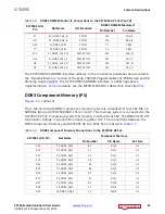
GPIO DIP Switch (SW12)
4-pole C&K SDA04H1SBD
38
25
ARM® core PJTAG Header (J64)
2x10 0.1inch male header, Samtec
TST-110-01-G-D
39
26
User PMOD GPIO Headers, page 60
PMOD Headers (J57, J58)
2x6 0.1 inch male header
37, 39
27
Power On/Off Slide Switch, page 62
Power On/Off Switch (SW1)
C&K 1201M2S3AQE2
48
28
FPGA PROG pushbutton (SW10)
E-Switch TL3301EF100QG
38
29
AP SoC MIO Config. DIP Switch (SW11)
5-pole DPDT CTS 206-125
15
30
FMC HPC connector (J37)
Samtec ASP_134486_01
24-27
31
FMC LPC connector (J5)
Samtec ASP_134603_01
28
32
Power Management System (top and bottom of
board)
TI UCD90120ARGC in conjunction
w/various regulators
48-57
33
XADC Analog-to-Digital Converter, page 83
XADC Connector (J63)
2x10 0.1inch male header, Samtec
TST-110-01-G-D
35
34
Programmable Logic JTAG Select Switch,
JTAG Configuration DIP Switch (SW4)
2-pole C&K SDA02H1SBD
16
35
JTAG Flying Lead Header (J62)
2x10 0.1inch male header, Samtec
TST-110-01-G-D
16
36
2x5 shrouded PMBus connector J4
ASSMAN HW10G-0202
48
37
2x7 2mm shrouded JTAG cable connector J3
MOLEX 87832-1420
16
38
12V power input 2x6 connector J22
MOLEX-39-30-1060
48
Notes:
1. Jumper header locations are identified in
Appendix A, Default Switch and Jumper Settings
.
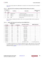
Table 1-1:
ZC706 Evaluation Board Component Descriptions
(Cont’d)
Callout
Feature
Notes
Schematic
0381513
Page Number


