background image

ZCU102 Evaluation Board User Guide

www.xilinx.com

57

UG1182 (v1.2) March 20, 2017

Chapter 3:

Board Component Descriptions

P05

9

IIC_MUX_RESET_B

RESET_B

3

U34, U135

TCA9548A

P06

10

GEM3_EXP_RESET_B

2A

3

U59

SN74LVC3G07

P10

13

FMC_HPC0_PRSNT_M2C_B

OE

4

U27, J5.H2

NC7SZ66, FMC0

P11

14

FMC_HPC1_PRSNT_M2C_B

OE

4

U24, J4.H2

NC7SZ66, FMC1

Table 3-20:

I2C0 Port Expander TCA6416A U97 Connections 

(Cont’d)

TCA6416A 

U97

Schematic Net Name

Connected To

Pin 

Name

Pin 

No.

Pin 

Name

Pin No.

Reference Designation

Device

Table 3-21:

I2C0 Multiplexer PCA9544A U60 (Addr. 

0x75

) Connections

U60 I2C Mux

Mux’d I2C Bus

Reference Designation

Device(s)

0

PS_PMBUS

U76, U77, U78, U87, U85, U86, U93, U88, U15, U92

INA226 Op amps

1

PL_PMBUS

U79, U81, U80, U84, U16, U65, U74, U75

INA226 Op amps

2

MAXIM_PMBUS

J84.3, U47, U7, U6, U10, U9, U63, U95, U96, U46, U4, U18, 

U13, U49

PMBUS connector, 

Voltage regulators

3

SYSMON

U135, U1

I2C1MUX, MPSoC

Table 3-22:

I2C0 U60 (Addr. 

0x75

) Mux Target Bus Connections

Reference 

Designation

Address

Device(s)

PS_PMBUS

U76

0X40

INA226 VCCPSINTFP

U77

0X41

INA226 VCCPSINTLP

U78

0X42

INA226 VCCPSAUX

U87

0X43

INA226 VCCPSPLL

U85

0X44

INA226 MGTRAVCC

U86

0X45

INA226 MGTRAVTT

U93

0X46

INA226 VCCO_PSDDR_504

U88

0X47

INA226 VCCOPS

U15

0X4A

INA226 VCCOPS3

U92

0X4B

INA226 VCCPSDDRPLL

PL_PMBUS

U79

0X40

INA226 VCCINT

U81

0X41

INA226 VCCBRAM

U80

0X42

INA226 VCCAUX

U84

0X43

INA226 VCC1V2

Send Feedback

Summary of Contents for ZCU102

Page 1: ...ZCU102 Evaluation Board User Guide UG1182 v1 2 March 20 2017...

Page 2: ...ing to MSP430 U41 in Table 3 17 Clarified references to Figure 3 17 in Table 3 19 and Table 3 20 Added addresses to titles in Table 3 21 and Table 3 22 and headings in Table 3 23 and Table 3 24 Change...

Page 3: ...Device Configuration 19 Chapter 3 Board Component Descriptions Overview 20 Component Descriptions 20 Zynq UltraScale XCZU9EG MPSoC 20 PS Side DDR4 SODIMM Socket 24 DDR4 Component Memory 29 PSMIO 32 Q...

Page 4: ...FPGA Mezzanine Card Interface 93 FMC HPC0 Connector J5 93 FMC HPC1 Connector J4 98 Cooling Fan Connector 104 VADJ_FMC Power Rail 104 TI MSP430 System Controller 105 Switches 107 ZCU102 Board Power Sy...

Page 5: ...ZCU102 Evaluation Board User Guide www xilinx com 5 UG1182 v1 2 March 20 2017 References 135 Please Read Important Legal Notices 136 Send Feedback...

Page 6: ...for rapid prototyping based on the Zynq UltraScale XCZU9EG 2FFVB1156I MPSoC multiprocessor system on chip High speed DDR4 SODIMM and component memory interfaces FMC expansion ports multi gigabit per s...

Page 7: ...35 37 40 SFP 2x2 Cage Page 34 FMC HPC0 GT Interface Pages 26 29 FMC HPC0 LA Bus Pages 26 29 FMC HPC0 LA Bus Pages 41 43 FMC HPC1 LA Bus Pages 30 33 HDMI TX Clock Pages 35 37 DDR4 Comp Memory 16 bit 1...

Page 8: ...card Configuration over JTAG with PC4 header Configuration over JTAG with ARM 20 pin header Configuration over USB to JTAG Bridge Clocks PL system PS_CLK Programmable Clock SMA SMA_GT_REF Ethernet USB...

Page 9: ...esigners a rapid prototyping platform utilizing the XCZU9EG 2FFVB1156I device The ZU9EG contains many useful processor system PS hard block peripherals exposed through the Multi use I O MIO interface...

Page 10: ...d documentation xdc listing schematics layout files and board outline fab drawings etc is available on the web at www xilinx com zcu102 Environmental Temperature Operating 0 C to 45 C Storage 25 C to...

Page 11: ...T Figure 2 1 is for visual reference only and might not reflect the latest revision of the board This user guide documents ZCU102 Rev 1 0 and later IMPORTANT There could be multiple revisions of this...

Page 12: ...rch 20 2017 Chapter2 BoardSetupandConfiguration X Ref Target Figure 2 1 Figure 2 1 ZCU102 Evaluation Board Components 5RXQG FDOORXW UHIHUHQFHV D FRPSRQHQW 2Q WKH IURQW VLGH RI WKH ERDUG 6TXDUH FDOORXW...

Page 13: ...uency Clock Generator PS Reference Clock I2C programmable any frequency clock generator Silicon Labs SI5341B B05071 GM 39 11 U20 SFP SFP Clock Recovery jitter attenuated clock Silicon Labs SI5328B C G...

Page 14: ...ment system top and bottom Maxim Regulators 59 86 35 P1 PCI Express Root Port Slot PCIe 4 lane connector FCI 10061913 101CLF 43 36 P11 DPAUX MIO 27 30 DisplayPort MOLEX 0472720001 44 37 J84 PMBus conn...

Page 15: ...gure 2 2 shows the board jumper header and DIP switch locations Each numbered component shown in the figure is keyed to Table 2 2 for default switch settings or Table 2 3 for default jumper settings B...

Page 16: ...DE0 ON ON OFF ON 26 12 SW8 MSP430 GPIO 5 POLE ON GND OFF Open 1 SW0 2 SW1 3 SW2 4 SW3 5 SW4 OFF OFF OFF OFF OFF 27 38 SW13 GPIO 8 POLE OFF pull down ON pull up All OFF 28 53 Table 2 3 Default Jumper S...

Page 17: ...1 2 VSUPPLY VCCOPS3 1 8V OFF 9 22 J56 VCCO_PSDDR_504 select 1 2 Switched DDR4 VDDQ 3 4 Direct DDR4 VDDQ 1 2 10 24 J159 DDR4 Reset Suspend Enable 1 2 Suspend disabled Gate bypass 2 3 Suspend enabled 1...

Page 18: ...G 1 2 21 51 J88 ARM Trace VTREF 1 2 3 3V Open 0V 1 2 22 54 J38 ARM Trace power 1 2 3 3V Open 0V 1 2 23 54 J153 Power inhibit OFF rails power on normally 1 2 all rails except UTIL OFF OFF 24 59 J9 PS_D...

Page 19: ...iguration memory is accomplished by storing a valid Zynq UltraScale MPSoC boot image into the Quad SPI flash devices connected to the MIO Quad SPI interface setting the boot mode pins SW6 4 1 QSPI32 s...

Page 20: ...ful processing system PS and user programmable logic PL into the same device The processing system in a Zynq UltraScale MPSoC features the ARM flagship Cortex A53 64 bit quad core processor and Cortex...

Page 21: ...U ACP 1 MB L2 GPU Mali 400 MP2 64 KB L2 2 x USB 3 0 NAND x8 ONFI 3 1 2 x SD3 0 eMMC4 51 Quad SPI x 8 2 x SPI 2 x CAN 2 x I2C 2 x UART GPIOs SYSMON MIO Central Switch FPD DMA PCIe Gen4 DisplayPort v1 2...

Page 22: ...ace with video resolution up to 4K x 2K 30 300 MHz pixel rate USB 3 0 interface compliant to USB 3 0 specification implementing a 5 Gb s line rate Serial GMII interface supports a 1 Gb s SGMII interfa...

Page 23: ...TS518FE rechargeable 1 5V lithium button type battery B1 is soldered to the board with the positive output connected to the XCZU9EG MPSoC U1 VCC_PSBATT pin AA22 The battery supply current IBATT speci...

Page 24: ...PSoC Configuration Bank 0 PL Bank 44 VCC3V3 3 3V GPIO DIP SW PB SW LEDs 74 25 MHz CLK PL Bank 47 VCC3V3 3 3V GPIO PMOD0 RT ANG FEMALE PMOD1 STR MALE PL I2C1 TRACEDATA 125 MHz CLK PL Bank 48 VCC3V3 3 3...

Page 25: ...Name AP29 DDR4_SODIMM_A0 144 A0 AP30 DDR4_SODIMM_A1 133 A1 AP26 DDR4_SODIMM_A2 132 A2 AP27 DDR4_SODIMM_A3 131 A3 AP25 DDR4_SODIMM_A4 128 A4 AN24 DDR4_SODIMM_A5 126 A5 AM29 DDR4_SODIMM_A6 127 A6 AM28 D...

Page 26: ..._DQ25 71 DQ25 AG24 DDR4_SODIMM_DQ26 83 DQ26 AG23 DDR4_SODIMM_DQ27 84 DQ27 AK22 DDR4_SODIMM_DQ28 66 DQ28 AJ21 DDR4_SODIMM_DQ29 67 DQ29 AJ22 DDR4_SODIMM_DQ30 79 DQ30 AK23 DDR4_SODIMM_DQ31 80 DQ31 AG31 D...

Page 27: ...IMM_DQ60 232 DQ60 AD32 DDR4_SODIMM_DQ61 233 DQ61 AD34 DDR4_SODIMM_DQ62 245 DQ62 AD33 DDR4_SODIMM_DQ63 246 DQ63 AN31 DDR4_SODIMM_CB0 92 CB0 NC AP31 DDR4_SODIMM_CB1 91 CB1 NC AP32 DDR4_SODIMM_CB2 101 CB...

Page 28: ...M_DQS6_T 221 DQS6_T AK32 DDR4_SODIMM_DQS6_C 219 DQS6_C AE32 DDR4_SODIMM_DQS7_T 242 DQS7_T AE33 DDR4_SODIMM_DQS7_C 240 DQS7_C AN32 DDR4_SODIMM_DQS8_T 97 DQS8_T AN33 DDR4_SODIMM_DQS8_C 95 DQS8_C AN27 DD...

Page 29: ...upplied from sink source regulator U35 The connections between the DDR4 memory and XCZU9EG bank 64 are listed in Table 3 4 AN28 DDR4_SODIMM_CS0_B 149 CS0_N AL30 DDR4_SODIMM_CS1_B 157 CS1_N Table 3 4 D...

Page 30: ...CI G2 DQL0 AK5 DDR4_DQ1 POD12_DCI F7 DQL1 AN4 DDR4_DQ2 POD12_DCI H3 DQL2 AM4 DDR4_DQ3 POD12_DCI H7 DQL3 AP4 DDR4_DQ4 POD12_DCI H2 DQL4 AP5 DDR4_DQ5 POD12_DCI H8 DQL5 AM5 DDR4_DQ6 POD12_DCI J3 DQL6 AM6...

Page 31: ...2 DDR4 component interface is a 40 impedance implementations Other memory interface details are also available in the UltraScale Architecture FPGAs Memory Interface Solutions Product Guide PG150 Ref 4...

Page 32: ...24 MIO42_SDIO_DIR_DAT1 SD1 MIO68 B26 MIO68_ENET_TX_D3 GEM3 MIO15 AN16 MIO15_I2C0_SDA I2C0 MIO41 J24 MIO41_SDIO_DIR_DAT0 SD1 MIO67 B25 MIO67_ENET_TX_D2 GEM3 MIO14 AL16 MIO14_I2C0_SCL I2C0 MIO40 M23 MIO...

Page 33: ...age 1 8V Datapath width 8 bits Data rate Various depending on Single Dual Quad mode The connections between the SPI flash memory and the XCZU9EG MPSoC are listed in Table 3 6 The configuration and Qua...

Page 34: ...host computer micro B connector to ZCU102 board connector J96 The USB3320 is a high speed USB 2 0 PHY supporting the UTMI low pin interface ULPI interface standard The ULPI standard defines the interf...

Page 35: ...kW Over voltage protection J110 CVBUS select Position 1 2 OTG and Device mode 1 mF Position 2 3 Host mode 120 F VBUS load capacitance J109 Cable ID select Position 1 2 A B cable detect Position 2 3 I...

Page 36: ...s a Micrel MIC2544 high side programmable current limit switch U121 This switch has an open drain output fault flag on pin 2 which will turn on LED DS51 if overcurrent or thermal shutdown conditions a...

Page 37: ...de documented in the Zynq UltraScale MPSoC Technical Reference Manual UG1085 Ref 2 The SDIO signals are connected to XCZU9EG MPSoC PS bank 501 which has its VCCMIO set to 1 8V Each of the six MIOxx_SD...

Page 38: ...DATA2_H 19 E5 DATA1_SD 20 D5 DATA0_SD 21 C5 CLK_SD 22 D4 CMD_SD 23 B5 DATA3_SD 24 A5 DATA2_SD 25 C2 ENABLE Table 3 9 U133 IP4856CX25 Adapter Pin Out Cont d Aires Adapter Pin Number IP4856CX25 U133 Pin...

Page 39: ...3 J25 MIO46_SDIO_DAT0 13 DATA0_H L25 MIO47_SDIO_DAT1 16 DATA1_H M25 MIO48_SDIO_DAT2 18 DATA2_H K25 MIO49_SDIO_DAT3 15 DATA3_H P25 MIO50_SDIO_CMD 4 CMD_H N25 MIO51_SDIO_CLK 1 CLK_IN N24 MIO44_SDIO_PROT...

Page 40: ...J8 2x7 2 mm shrouded keyed JTAG pod flat cable connector J6 2x10 ARM JTAG male pin header The ZCU102 board JTAG chain is shown in Figure 3 6 X Ref Target Figure 3 6 Figure 3 6 JTAG Chain Block Diagram...

Page 41: ...Switch U27 adds an attached FMC to the JTAG chain as determined by the FMC_HPC0_PRSNT_M2C_B signal Switch U24 adds an attached FMC to the JTAG chain as determined by the FMC_HPC1_PRSNT_M2C_B signal T...

Page 42: ...CMOS33 28 H21 TRACEDATA2 LVCMOS33 26 H18 TRACEDATA3 LVCMOS33 24 H19 TRACEDATA4 LVCMOS33 22 J17 TRACEDATA5 LVCMOS33 20 H17 TRACEDATA6 LVCMOS33 18 L18 TRACEDATA7 LVCMOS33 16 G18 TRACEDATA8 LVCMOS33 37 G...

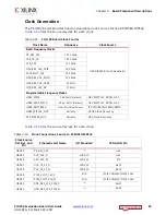
Page 43: ...REF_CLK_USB3 24 MHz GTR_REF_CLK_DP 27 MHz Programmable Frequency Clocks USER_SI570 300 MHz Default U42 SI570 I2C PROG OSC USER_MGT_SI570 156 2 MHz Default U56 SI570 I2C PROG OSC USER_MGT_SMA User Prov...

Page 44: ...N 2 U28 U69 24 GTR_REF_CLK_DP_P 2 U31 U69 23 GTR_REF_CLK_DP_N 2 U32 U42 4 USER_SI570_P DIFF_SSTL12 AL8 U42 5 USER_SI570_N DIFF_SSTL12 AL7 U56 4 USER_MGT_SI570_P 2 1 to 2 CLOCK BUFFER U51 6 U56 5 USER_...

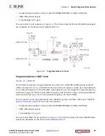
Page 45: ...is connected to XCZU9EG MPSoC U1 pins AL8 and AL7 respectively On power up the user clock defaults to an output frequency of 300 000 MHz User applications can change the output frequency within the ra...

Page 46: ...U51 On power up the user clock defaults to an output frequency of 156 250 MHz User applications can change the output frequency within the range of 10 MHz to 810 MHz through an I2C interface Power cy...

Page 47: ...nto FPGA U1 MGTH bank 129 This differential signal pair is series capacitor coupled The P side SMA J79 signal USER_SMA_MGT_CLOCK_P is connected to U1 MGTREFCLK0P pin J27 with the N side SMA J80 signal...

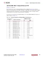
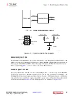
Page 48: ...t interface shown in Figure 3 12 which connects to a TI DP83867IRPAP Ethernet RGMII PHY before being routed to an RJ45 Ethernet connector The RGMII Ethernet PHY is boot strapped to PHY address 5 b0110...

Page 49: ...hernet connections from XCZU9EG MPSoC U1 to the DP83867IRPAP PHY device at U98 are listed in Table 3 14 Table 3 14 Ethernet Connections XCZU9EG MPSoC to the PHY Device XCZU9EG U1 Pin Schematic Net Nam...

Page 50: ...d with a LEDCR1 register write available via the PHY s management Data Interface MDIO MDC LED_2 is assigned to ACT activity indicator and X Ref Target Figure 3 13 Figure 3 13 Ethernet PHY Reset Circui...

Page 51: ...ART on the ZCU102 board provides four level shifted UART connections through single micro B USB connector J83 Channel 0 and 1 are PS side MIO connections described in the MIO section Channel 2 is a PL...

Page 52: ...5 The connections from XCZU9EG MPSoC U1 to CP2108 U40 via TSX0104E level shifter U52 are listed in Table 3 16 X Ref Target Figure 3 15 Figure 3 15 PL Side USB UART Interface Table 3 16 XCZU9EG U1 to C...

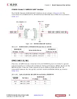
Page 53: ...e Zynq UltraScale MPSoC device and the MSP430 system controller These signals are level shifted by TSX0108E U141 The connections between the U41 system controller and the XCZU9EG MPSoC are listed in T...

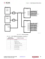
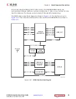
Page 54: ...rapped to respond to I2C address 0x20 and U61 to 0x21 The PCA9544A multiplexer is set to 0x75 The I2C0 bus also provides access to the PMBUS power controllers and PS side and PL side INA226 power moni...

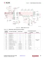
Page 55: ...C_EN MGTRAVTT_EN VCCPSDDRPLL_EN MI026_PMU_INPUT_LS PS_GTR_LANE_SEL0 PS_GTR_LANE_SEL1 PS_GTR_LANE_SEL2 PS_GTR_LANE_SEL3 PCIE_CLK_DIR_SEL IIC_MUX_RESET_B GEM3_EXP_RESET_B FMC_HPC0_PRSNT_M2C_B 8 6 6 8 3...

Page 56: ...93 INA226 Op amps P07 11 MAXIM_PMBUS_ALERT ALERT 9 11 13 J84 7 U4 U8 U7 U9 U10 U13 U18 U46 U47 U49 U63 U95 U96 MAX15301 9 MAX15303 11 MAX20751 13 P10 13 PL_DDR4_VTERM_EN EN 7 U35 TPS51200 P11 14 PL_DD...

Page 57: ...Bus Reference Designation Device s 0 PS_PMBUS U76 U77 U78 U87 U85 U86 U93 U88 U15 U92 INA226 Op amps 1 PL_PMBUS U79 U81 U80 U84 U16 U65 U74 U75 INA226 Op amps 2 MAXIM_PMBUS J84 3 U47 U7 U6 U10 U9 U63...

Page 58: ...5 INA226 VADJ_FMC U74 0X46 INA226 MGTAVCC U75 0X47 INA226 MGTAVTT MAXIM_PMBUS J84 N A PMBUS Conn SDA Pin 3 SCL Pin 1 U47 0X13 MAX15301 VCCINT U7 0X14 MAX15303 VCCBRAM U6 0X15 MAX15303 VCCAUX U10 0X16...

Page 59: ...DA SCL SI5341_SDA SCL USER_S1570_SDA SCL USER_MGT_SI570_SDA SCL S15328_SDA SCL FMC_HPC0_IIC_SDA SCL FMC_HPC1_IIC_SDA SCL SYSMON_SDA SCL DDR4_SODIMM_SDA SCL SFP3_IIC_SDA SCL SFP2_IIC_SDA SCL SFP1_IIC_S...

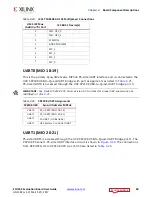
Page 60: ...meration as identified in Table 3 25 UART1 MIO 20 21 PS side UART1 is accessed through the U40 CP2108 USB to Quad UART Bridge port 1 The CP2108 Channel 1 PS side UART interface circuit is shown in Fig...

Page 61: ...tor U33 and TI SN65HVD232 CAN bus transceiver U122 before being presented to the user on 0 1 inch centered 8 pin male header J98 see Figure 3 20 and Figure 3 21 X Ref Target Figure 3 19 Figure 3 19 CP...

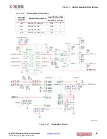
Page 62: ...ynq UltraScale MPSoC provides a VESA DisplayPort 1 2 source only controller that supports up to two lanes of main link data at rates of 1 62 Gb s 2 70 Gb s or 5 40 Gb s The DisplayPort standard define...

Page 63: ...ComponentDescriptions Table 3 27 DPAUX MIO Connections XCZU9EG U1 Pin Schematic Net Name Level Shifter U114 Pin Name Pin No L21 MIO30_DP_AUX_IN 2A1 8 K22 MIO29_DP_OE 1A2 7 N21 MIO28_DP_HPD 2A2 9 M21 M...

Page 64: ...Technical Reference Manual UG1085 Ref 2 for more details about the PMU interface HDMI Video Output Figure 2 1 callout 14 The ZCU102 board provides a high definition multimedia interface HDMI video ou...

Page 65: ...ture can be turned off through I2C programming The HDMI video output block diagram is shown in Figure 3 23 the interface circuit in Figure 3 24 The connections between the codec and the XCZU9EG MPSoC...

Page 66: ...Component Pin No Pin Name Device T29 HDMI_TX0_P 1 8 IN_D0P SN65DP159 U94 T30 HDMI_TX0_N 1 9 IN_D0N R31 HDMI_TX1_P 1 5 IN_D1P R32 HDMI_TX1_N 1 6 IN_D1N P29 HDMI_TX2_P 1 2 IN_D2P P30 HDMI_TX2_N 1 3 IN_...

Page 67: ...24 CEC_A TPD12S016RK U70 B16 HDMI_TX_HPD LVCMOS33 3 HPD_A H12 HDMI_SI5324_LOL LVCMOS33 18 LOL SI5324C U108 J12 HDMI_SI5324_RST LVCMOS33 1 RST_B F11 HDMI_SI5324_INT_ALM LVCMOS33 3 INT_C1B AG5 HDMI_REC_...

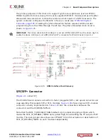
Page 68: ...bs Si5324C U108 pin 1 reset net HDMI_SI5324_RST must be driven High to enable the device U108 pin 1 net HDMI_SI5324_RST is connected to FPGA U1 bank 50 pin J12 SFP SFP Connector Figure 2 1 callout 17...

Page 69: ...P0 E4 SFP0_TX_P RT18 RT_TD_P E3 SFP0_TX_N RT19 RT_TD_N D2 SFP0_RX_P RT13 RT_RD_P D1 SFP0_RX_N RT12 RT_RD_N A12 SFP0_TX_DISABLE 1 RT3 RT_ TX_DISABLE Location Right Lower SFP1 D6 SFP1_TX_P RL18 RL_TD_P...

Page 70: ...ynchronous protocols such as CPRI or OBSAI to perform clock recovery from a user supplied SFP SFP module and use the jitter attenuated recovered clock to drive the reference clock inputs of a GTH tran...

Page 71: ...ports two PMOD GPIO headers J55 right angle female and J87 vertical male The PMOD nets are wired to the XCZU9EG device U1 bank 47 Figure 3 28 shows the GPIO PMOD headers J55 and J87 Table 3 31 lists t...

Page 72: ...J3 with its MPSoC U1 Bank 50 connections Table 3 31 XCZU9EG U1 to PMOD Connections XCZU9EG U1 Pin Schematic Net Name I O Standard PMOD Pin A20 PMOD0_0 LVCMOS33 J55 1 B20 PMOD0_1 LVCMOS33 J55 3 A22 PM...

Page 73: ...Prototype Header J3 Connections to the XCZU9EG MPSoC XCZU9EG U1 Pin Schematic Net Name I O Standard Prototype Header J3 Pin J15 L12N_AD8N_50_N LVCMOS33 14 J16 L12N_AD8P_50_P LVCMOS33 16 G16 L11N_AD9N_...

Page 74: ...f the I2C0 main bus see Figure 3 17 and I2C0 MIO 14 15 page 54 for more details User I O Figure 2 1 callouts 21 23 The ZCU102 board provides these user and general purpose I O capabilities Eight user...

Page 75: ...Chapter3 BoardComponentDescriptions Figures Figure 3 31 through Figure 3 33 show the GPIO circuits and Table 3 33 lists the GPIO to XCZU9EG U1 connections X Ref Target Figure 3 31 Figure 3 31 GPIO LE...

Page 76: ..._1 LVCMOS33 DS37 2 AE13 GPIO_LED_2 LVCMOS33 DS39 2 AJ14 GPIO_LED_3 LVCMOS33 DS40 2 AJ15 GPIO_LED_4 LVCMOS33 DS41 2 AH13 GPIO_LED_5 LVCMOS33 DS42 2 AH14 GPIO_LED_6 LVCMOS33 DS43 2 AL12 GPIO_LED_7 LVCMO...

Page 77: ...ization was successful Red FPGA initialization is in progress DS2 VCC12_SW Green 12VDC Power ON DS3 VCCAUX_PGOOD Green VCCAUX 1 8VDC Power ON DS4 VCC3V3_PGOOD Green VCC3V3 3 3VDC Power ON DS5 VCCINT_P...

Page 78: ...icates a secure lockdown state Alternatively it can be used by the PMU firmware to indicate system status DS34 DP_VCC3V3 Green Display Port 3 3VDC Power ON DS35 PS_ERR_OUT 1 Red PS error out is assert...

Page 79: ...de The GTH transceivers in the XCZU9EG device are grouped into four channels referred to as Quads The reference clock for a Quad can be sourced from the Quad above or Quad below the GTH Quad of intere...

Page 80: ...EFCLK1 USER_SMA_MGT_CLOCK_C_P N Contains 4 GTH transceivers allocated to FMC_HPC1_DP 4 7 _C2M M2C_P N Quad 130 MGTREFCLK0 FMC_HPC1_GBTCLK0_M2C_P N MGTREFCLK1 FMC_HPC1_GBTCLK1_M2C_P N Contains 4 GTH tr...

Page 81: ...le Si570 clock and a user provided SMA clock The MGT reference clocks are located in adjacent MGT banks 128 129 and 130 X Ref Target Figure 3 35 Figure 3 35 GTH Bank Assignments 0 7B B 0 7B B 0 7B B 0...

Page 82: ...interface This I2C interface is accessible for each individual SFP module through the I2C multiplexer topology on the ZCU102 HDMI Three 3 PL side GTH transceivers are dedicated for HDMI source and sin...

Page 83: ...I BOTTOM PORT P7 T34 MGTHRXN0_128 HDMI_RX0_C_N 1 B9 TMDS_DATA0_N P33 MGTHRXP1_128 HDMI_RX1_C_P 1 B4 TMDS_DATA1_P P34 MGTHRXN1_128 HDMI_RX1_C_N 1 B6 TMDS_DATA1_N N31 MGTHRXP2_128 HDMI_RX2_C_P 1 B1 TMDS...

Page 84: ...A18 DP5_M2C_P K34 MGTHRXN1_129 FMC_HPC1_DP5_M2C_N A19 DP5_M2C_N H29 MGTHTXP2_129 FMC_HPC1_DP6_C2M_P B36 DP6_C2M_P H30 MGTHTXN2_129 FMC_HPC1_DP6_C2M_N B37 DP6_C2M_N H33 MGTHRXP2_129 FMC_HPC1_DP6_M2C_P...

Page 85: ...MC_HPC1_DP1_M2C_P A2 DP1_M2C_P D34 MGTHRXN1_130 FMC_HPC1_DP1_M2C_N A3 DP1_M2C_N B29 MGTHTXP2_130 FMC_HPC1_DP2_C2M_P A26 DP2_C2M_P B30 MGTHTXN2_130 FMC_HPC1_DP2_C2M_N A27 DP2_C2M_N C31 MGTHRXP2_130 FMC...

Page 86: ..._N A39 DP5_C2M_N P2 MGTHRXP1_228 FMC_HPC0_DP5_M2C_P A18 DP5_M2C_P P1 MGTHRXN1_228 FMC_HPC0_DP5_M2C_N A19 DP5_M2C_N N4 MGTHTXP2_228 FMC_HPC0_DP7_C2M_P B32 DP7_C2M_P N3 MGTHTXN2_228 FMC_HPC0_DP7_C2M_N B...

Page 87: ...P1_C2M_N A23 DP1_C2M_N J4 MGTHRXP1_229 FMC_HPC0_DP1_M2C_P A2 DP1_M2C_P J3 MGTHRXN1_229 FMC_HPC0_DP1_M2C_N A3 DP1_M2C_N G4 MGTHTXP2_229 FMC_HPC0_DP0_C2M_P C2 DP0_C2M_P G3 MGTHTXN2_229 FMC_HPC0_DP0_C2M_...

Page 88: ...SFP0_TX_N RT19 RT_TD_N D2 MGTHRXP0_230 SFP0_RX_P RT13 RT_RD_P D1 MGTHRXN0_230 SFP0_RX_N RT12 RT_RD_N D6 MGTHTXP1_230 SFP1_TX_P RL18 RL_TD_P D5 MGTHTXN1_230 SFP1_TX_N RL19 RL_TD_N C4 MGTHRXP1_230 SFP1...

Page 89: ...Pericom GT switch settings via PS side I2C0 and the external GPIO port expander The functionality of each ZU9EG GTR lane is controlled through the MPSoC s ICM and is defined in the Zynq UltraScale MP...

Page 90: ...1 x1 DisplayPort 1 Lane USB SATA Table 3 41 XCZU9EG Interconnect Matrix Protocol PHY Lane 0 PHY Lane 1 PHY Lane 2 PHY Lane 3 PCIe PCIe 0 PCIe 0 PCIe 0 PCIe 0 SATA SATA 0 SATA 1 SATA 0 SATA 1 USB0 USB0...

Page 91: ...ction is controlled by the PS side I2C0 GPIO port expander U97 connected to the multiplexer s S input S 0 connects the A input to the B output whereas S 1 connects the A input to the C output The S se...

Page 92: ...s data transfers at the rate of 5 0 GT s for Gen2 applications The PCIe clock is routed as a 100 differential pair The PCIe transmit and receive signal data paths are routed with a differential charac...

Page 93: ...ementations of high pin count connectors at J5 HPC0 and J4 HPC1 HPC connectors use a 10 x 40 form factor populated with 400 pins The connectors are keyed so that a mezzanine card when installed in eit...

Page 94: ...4 NC A6 FMC_HPC0_DP2_M2C_P F2 B5 NC A7 FMC_HPC0_DP2_M2C_N F1 B8 NC A10 FMC_HPC0_DP3_M2C_P K2 B9 NC A11 FMC_HPC0_DP3_M2C_N K1 B12 FMC_HPC0_DP7_M2C_P M2 A14 FMC_HPC0_DP4_M2C_P L4 B13 FMC_HPC0_DP7_M2C_N...

Page 95: ...PC0_LA13_P LVCMOS18 AB8 C22 FMC_HPC0_LA18_CC_P LVCMOS18 N9 D18 FMC_HPC0_LA13_N LVCMOS18 AC8 C23 FMC_HPC0_LA18_CC_N LVCMOS18 N8 D20 FMC_HPC0_LA17_CC_P LVCMOS18 P11 C26 FMC_HPC0_LA27_P LVCMOS18 M10 D21...

Page 96: ...Net Name I O Standard U1 Pin E2 NC F1 FMC_HPC0_PG_M2C P U to 3 3V via R277 E3 NC F4 NC E6 NC F5 NC E7 NC F7 NC E9 NC F8 NC E10 NC F10 NC E12 NC F11 NC E13 NC F13 NC E15 NC F14 NC E16 NC F16 NC E18 NC...

Page 97: ...FMC_HPC0_LA11_P LVCMOS18 AB6 G19 FMC_HPC0_LA16_N LVCMOS18 AA12 H17 FMC_HPC0_LA11_N LVCMOS18 AB5 G21 FMC_HPC0_LA20_P LVCMOS18 N13 H19 FMC_HPC0_LA15_P LVCMOS18 Y10 G22 FMC_HPC0_LA20_N LVCMOS18 M13 H20 F...

Page 98: ...Two GBTCLK differential clocks Table 3 48 J5 HPC0 FMC Section J and K Connections to XCZU9EG U1 J5 Pin Schematic Net Name I O Standard U1 Pin J5 Pin Schematic Net Name I O Standard U1 Pin J2 NC K1 NC...

Page 99: ...D34 B4 NC A6 FMC_HPC1_DP2_M2C_P C31 B5 NC A7 FMC_HPC1_DP2_M2C_N C32 B8 NC A10 FMC_HPC1_DP3_M2C_P B33 B9 NC A11 FMC_HPC1_DP3_M2C_N B34 B12 FMC_HPC1_DP7_M2C_P F33 A14 FMC_HPC1_DP4_M2C_P L31 B13 FMC_HPC1...

Page 100: ...FMC_HPC1_LA13_P LVCMOS18 AG8 C22 FMC_HPC1_LA18_CC_P LVCMOS18 Y8 D18 FMC_HPC1_LA13_N LVCMOS18 AH8 C23 FMC_HPC1_LA18_CC_N LVCMOS18 Y7 D20 FMC_HPC1_LA17_CC_P LVCMOS18 Y5 C26 FMC_HPC1_LA27_P LVCMOS18 U10...

Page 101: ...Net Name I O Standard U1 Pin E2 NC F1 FMC_HPC0_PG_M2C P U to 3 3V via R250 E3 NC F4 NC E6 NC F5 NC E7 NC F7 NC E9 NC F8 NC E10 NC F10 NC E12 NC F11 NC E13 NC F13 NC E15 NC F14 NC E16 NC F16 NC E18 NC...

Page 102: ...MC_HPC1_LA16_P LVCMOS18 AG10 H16 FMC_HPC1_LA11_P LVCMOS18 AE8 G19 FMC_HPC1_LA16_N LVCMOS18 AG9 H17 FMC_HPC1_LA11_N LVCMOS18 AF8 G21 FMC_HPC1_LA20_P LVCMOS18 AB11 H19 FMC_HPC1_LA15_P LVCMOS18 AD10 G22...

Page 103: ...tions to XCZU9EG U1 J5 Pin Schematic Net Name I O Standard U1 Pin J5 Pin Schematic Net Name I O Standard U1 Pin J2 NC K1 NC J3 NC K4 NC J6 NC K5 NC J7 NC K7 NC J9 NC K8 NC J10 NC K10 NC J12 NC K11 NC...

Page 104: ...The valid values of the VADJ_FMC rail are 1 2V 1 5V and 1 8V At power on the system controller detects if an FMC module is connected to each interface If no cards are attached to the FMC ports the VAD...

Page 105: ...sident system controller user interface SCUI is provided on the ZCU102 web page This GUI enables you to query and control select programmable features such as clocks FMC functionality power systems an...

Page 106: ...the System Controller utility The MSP430 uses ID resistor encoding to allow the System Controller utility awareness of which board type is active See Table 3 54 for the configuration of the ID encodi...

Page 107: ...callout 28 The ZCU102 board power switch is SW1 Sliding the switch actuator from the Off to On position applies 12V power from J52 a 6 pin mini fit connector Green LED DS2 illuminates when the ZCU102...

Page 108: ...itch SW5 grounds the XCZU9EG MPSoC PS_PROG_B pin U21 when pressed see Figure 3 42 This action clears programmable logic configuration which the PS software can then act on See the Zynq UltraScale MPSo...

Page 109: ...essing and then releasing pushbutton SW3 causes net PS_SRST_B to strobe Low This reset is used to force a system reset It can be tied or pulled High and can be High during the PS supply power ramps Wh...

Page 110: ...ard Power System Figure 2 1 callout 34 The ZCU102 hosts a Maxim PMBus based power system Each individual Maxim MAX20751EKX MAX15301 or MAX15303 voltage regulator has a PMBus interface Figure 3 44 show...

Page 111: ...J_FMC 1 80V 0x45 65 MAX15027 U38 N A Maxim LDO Regulator 1A PL_DDR4_VPP_2V5 2 5V N A 66 MAX20751EKX U95 0x72 Maxim multiphase master with smart slave VT77518 6A MGTAVCC 0 90V 0x46 67 MAX20751EKX U96 0...

Page 112: ...an be downloaded from the Maxim website This is the simplest and most convenient way to monitor the voltage and current values for the Maxim PMBus programmed power rails listed in Table 3 55 Each PMBu...

Page 113: ...er menu selections The Maxim controller PMBus is also accessible by the system controller which can also display the rail voltage measurement made by its sourcing Maxim controller User IP in the PL ca...

Page 114: ...he FPGA mezzanine card FMC high pin count HPC connector defined by the VITA 57 1 FMC specification For a description of how the ZCU102 evaluation board implements the FMC specification see FPGA Mezzan...

Page 115: ...FMC connectors J5 HPC0 and J4 HPC1 are connected to MPSoC banks powered by the variable voltage VAJ_FMC Because different FMC cards implement different circuitry the FMC bank I O standards must be uni...

Page 116: ...N N27 get_ports HDMI_RX_CLK_C_P set_property PACKAGE_PIN N28 get_ports HDMI_RX_CLK_C_N MGTH 129 HPC1_DP 4 7 set_property PACKAGE_PIN L27 get_ports USER_MGT_SI570_CLOCK1_C_P set_property PACKAGE_PIN L2...

Page 117: ...net PACKAGE_PIN AN27 DDR4_SODIMM_CK0_C Bank 504 PS_DDR_CK_N0 Other net PACKAGE_PIN AL27 DDR4_SODIMM_CK1_C Bank 504 PS_DDR_CK_N1 Other net PACKAGE_PIN AN26 DDR4_SODIMM_CK0_T Bank 504 PS_DDR_CK0 Other...

Page 118: ...net PACKAGE_PIN AE27 DDR4_SODIMM_DQ40 Bank 504 PS_DDR_DQ40 Other net PACKAGE_PIN AF28 DDR4_SODIMM_DQ41 Bank 504 PS_DDR_DQ41 Other net PACKAGE_PIN AF30 DDR4_SODIMM_DQ42 Bank 504 PS_DDR_DQ42 Other net P...

Page 119: ...A0 set_property IOSTANDARD SSTL12_DCI get_ports DDR4_A0 set_property PACKAGE_PIN AM9 get_ports DDR4_A1 set_property IOSTANDARD SSTL12_DCI get_ports DDR4_A1 set_property PACKAGE_PIN AP8 get_ports DDR4_...

Page 120: ...DQ12 set_property PACKAGE_PIN AM1 get_ports DDR4_DQ13 set_property IOSTANDARD POD12_DCI get_ports DDR4_DQ13 set_property PACKAGE_PIN AP3 get_ports DDR4_DQ14 set_property IOSTANDARD POD12_DCI get_ports...

Page 121: ...s FMC_HPC0_CLK1_M2C_P set_property PACKAGE_PIN G7 get_ports FMC_HPC0_GBTCLK0_M2C_C_N set_property PACKAGE_PIN G8 get_ports FMC_HPC0_GBTCLK0_M2C_C_P set_property PACKAGE_PIN L7 get_ports FMC_HPC0_GBTCL...

Page 122: ...t_ports FMC_HPC0_LA04_P set_property PACKAGE_PIN AC3 get_ports FMC_HPC0_LA05_N set_property IOSTANDARD LVCMOS18 get_ports FMC_HPC0_LA05_N set_property PACKAGE_PIN AB3 get_ports FMC_HPC0_LA05_P set_pro...

Page 123: ...rts FMC_HPC0_LA19_P set_property IOSTANDARD LVCMOS18 get_ports FMC_HPC0_LA19_P set_property PACKAGE_PIN M13 get_ports FMC_HPC0_LA20_N set_property IOSTANDARD LVCMOS18 get_ports FMC_HPC0_LA20_N set_pro...

Page 124: ...CLK0_M2C_N set_property PACKAGE_PIN AE7 get_ports FMC_HPC1_CLK0_M2C_P set_property IOSTANDARD LVDS get_ports FMC_HPC1_CLK0_M2C_P set_property PACKAGE_PIN P9 get_ports FMC_HPC1_CLK1_M2C_N set_property...

Page 125: ...get_ports FMC_HPC1_LA03_P set_property IOSTANDARD LVCMOS18 get_ports FMC_HPC1_LA03_P set_property PACKAGE_PIN AF1 get_ports FMC_HPC1_LA04_N set_property IOSTANDARD LVCMOS18 get_ports FMC_HPC1_LA04_N...

Page 126: ..._LA18_CC_N set_property PACKAGE_PIN Y8 get_ports FMC_HPC1_LA18_CC_P set_property IOSTANDARD LVCMOS18 get_ports FMC_HPC1_LA18_CC_P set_property PACKAGE_PIN AA10 get_ports FMC_HPC1_LA19_N set_property I...

Page 127: ...ty PACKAGE_PIN R28 get_ports HDMI_SI5324_OUT_C_N set_property PACKAGE_PIN R27 get_ports HDMI_SI5324_OUT_C_P set_property PACKAGE_PIN AG4 get_ports HDMI_REC_CLOCK_C_N set_property IOSTANDARD LVDS get_p...

Page 128: ...CKAGE_PIN D17 get_ports TRACETRST_B set_property IOSTANDARD LVCMOS33 get_ports TRACETRST_B set_property PACKAGE_PIN E18 get_ports TRACEDATA15 set_property IOSTANDARD LVCMOS33 get_ports TRACEDATA15 set...

Page 129: ...et_property PACKAGE_PIN AK13 get_ports GPIO_DIP_SW7 set_property IOSTANDARD LVCMOS33 get_ports GPIO_DIP_SW7 set_property PACKAGE_PIN AL13 get_ports GPIO_DIP_SW6 set_property IOSTANDARD LVCMOS33 get_po...

Page 130: ...erty IOSTANDARD LVCMOS33 get_ports PMOD1_1 set_property PACKAGE_PIN D22 get_ports PMOD1_2 set_property IOSTANDARD LVCMOS33 get_ports PMOD1_2 set_property PACKAGE_PIN E22 get_ports PMOD1_3 set_property...

Page 131: ...PACKAGE_PIN E3 get_ports SFP0_TX_N set_property PACKAGE_PIN E4 get_ports SFP0_TX_P set_property PACKAGE_PIN A12 get_ports SFP0_TX_DISABLE set_property IOSTANDARDLVCMOS33 get_ports SFP0_TX_DISABLE SFP1...

Page 132: ...y IOSTANDARD LVCMOS33 get_ports PL_DP_OE set_property PACKAGE_PIN H11 get_ports PL_DP_HPD set_property IOSTANDARD LVCMOS33 get_ports PL_DP_HPD set_property PACKAGE_PIN D10 get_ports PL_DPAUX_OUT set_p...

Page 133: ...ements for the PC Test Environment www xilinx com support answers 66752 Declaration of Conformity The Zynq UltraScale ZCU102 Declaration of Conformity is online For Technical Support please open a Sup...

Page 134: ...dequate measures Safety IEC 60950 1 2005 Information technology equipment Safety Part 1 General requirements EN 60950 1 2006 Information technology equipment Safety Part 1 General requirements Marking...

Page 135: ...date information related to the ZCU102 board and its documentation is available on the following websites ZCU102 Evaluation Kit ZCU102 Evaluation Kit Master Answer Record AR 66752 These Xilinx documen...

Page 136: ...les Please Read Important Legal Notices The information disclosed to you hereunder the Materials is provided solely for the selection and use of Xilinx products To the maximum extent permitted by appl...

Page 137: ...DEPLOYMENT OF AIRBAGS OR FOR USE IN APPLICATIONS THAT AFFECT CONTROL OF A VEHICLE SAFETY APPLICATION UNLESS THERE IS A SAFETY CONCEPT OR REDUNDANCY FEATURE CONSISTENT WITH THE ISO 26262 AUTOMOTIVE SAF...

Reviews: