


1. GENERAL INFORMATION
·
·
·
·
·
·
·
·
·
·
·
·
·
·
·
·
·
·
·
·
·
·
·
·
·
·
·
·
·
·
·
1
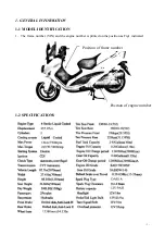
1-1 MODEL IDENTIFICATION
·
···
··
···
···
··
···
···
··
···
····
1
1-2 SPECIFICATIONS
··
···
··
···
···
··
···
···
··
···
···
··
···
··
·
1
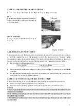
1-3 FUEL AND OIL RECOMMENDATIONS
·
·
·
·
·
·
·
·
·
·
·
·
·
·
·
·
·
·
2
1-4 BREAKING-IN PROCEDURE
···
··
···
···
··
···
···
··
···
··
·
2
1-5 PRECAUTIONS AND GENERAL INSTRUCTION
·
·
·
·
·
·
·
·
·
·
2
1-6 Use OF GENUINE PARTS
·
·
·
·
·
·
·
·
·
·
·
·
·
·
·
·
·
·
·
·
·
·
·
·
·
·
·
·
·
·
3
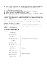
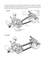
1-7 POWER TRANSMISSION
··
···
···
···
···
··
···
···
··
···
···
3
2
.
PERIODIC MAINTENANCE AND TUNE-UP PROCEDURETHE
·
6
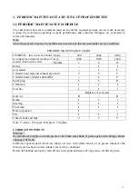
2-1 PERIODIC MAINTENANCE SCHEDULE
···
···
···
··
···
···
6
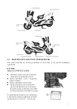
2-2 MAINTENANCE AND TUNE-UP PROCEDURE
···
··
···
···
·
7
BATTERY
···
··
···
···
··
···
···
··
···
···
··
···
···
··
···
···
·
7
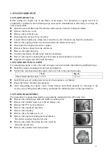
AIR CLEANER
·
·
·
·
·
·
·
·
·
·
·
·
·
·
·
·
·
·
·
·
·
·
·
·
·
·
·
·
·
·
·
·
·
·
·
·
·
·
·
8
CYLINDER HEAD NUTS AND EXHAUST PIPE BOLTS
·
·
·
·
8
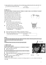
SPARK PLUG
·
·
·
·
·
·
·
·
·
·
·
·
·
·
·
·
·
·
·
·
·
·
·
·
·
·
·
·
·
·
·
·
·
·
·
·
·
·
·
·
9
CARBURETOR
·
···
···
··
···
···
··
···
···
··
···
···
··
···
···
9
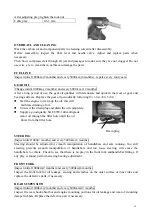
FUEL LINE
·
·
·
·
·
·
·
·
·
·
·
·
·
·
·
·
·
·
·
·
·
·
·
·
·
·
·
·
·
·
·
·
·
·
·
·
·
·
·
·
·
10
GEAR OIL
·
·
·
·
·
·
·
·
·
·
·
·
·
·
·
·
·
·
·
·
·
·
·
·
·
·
·
·
·
·
·
·
·
·
·
·
·
·
·
·
·
·
10
STEERING
··
··
···
···
··
···
···
··
···
···
··
···
···
··
···
··
·
10
FRONT FORK
··
···
···
··
···
···
··
···
···
··
···
···
··
···
·
·
10
REAR SUSPENSION
·
·
·
·
·
·
·
·
·
·
·
·
·
·
·
·
·
·
·
·
·
·
·
·
·
·
·
·
·
·
·
·
·
10
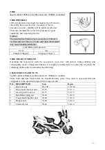
TIRE
·
·
·
·
·
·
·
·
·
·
·
·
·
·
·
·
·
·
·
·
·
·
·
·
·
·
·
·
·
·
·
·
·
·
·
·
·
·
·
·
·
·
·
·
·
·
·
11