20
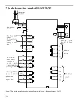
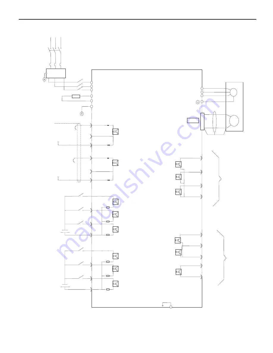
7. Standard connection example of DS2-45P5&47P5
Note: This is the standard connection diagram of open collector input (+24V).
3.3K
Ω
3.3K
Ω
3.3K
Ω
3.3K
Ω
3.3K
Ω
3.3K
Ω
FLT
M
PG
R
S
T
U
V
W
PE
PUL- CN0-1
DIR- CN0-4
V1+ CN0-3
CN2
P+
/SON CN0-7
/ALMRS CN0-8
/POT CN0-9
+24V CN0-10
PB
+24V CN1-5
CN1-10
CN1-9
CN1-8
CN1-13
CN3-1
CN3-2
CN3-3
CN1-6
CN1-7
COIN
COM
ALM
S-RDY
COM
Z0
B0
A0
GND
(50/60HZ)
Regenerative
resistor
The shield layer
connect
0V at signal side,
connect
nothing at servo
side
Servo enable
(ON is enable)
Alarm reset
(clear the alarm when ON)
Forward prohibited
(forward prohibited when ON)
Reverse prohibited
(reverse prohibited when ON)
Speed choice
Speed choice
Well operate with
the end of shield
cable
Encoder
output
Self-defined
output
PE
U
V
W
150
Ω
CN0-2
24V
V1+ CN0-6
24V
CN0-5
3.3K
Ω
3.3K
Ω
150
Ω
/N-OT CN1-2
/SPD-A CN1-3
/SPD-B CN1-4
3-phase 380V


