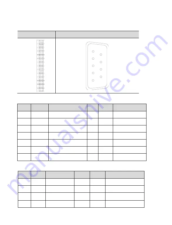
3-2. Control terminals
The serial numbers of the following connectors are in the order of viewing the welding side.
CN0
CN1
P-
P+5V
P+24V
D-
D+5V
D+24V
SI1
SI2
SI3
SI4
+24V
SO1
SO2
COM
1
5 9
6
CN0 terminals
No.
Name
Explanation
No.
Name Explanation
1
P-
Pulse input PUL-
8
SI2
Input 2
2
P+5V
5V difference input
9
SI3
Input 3
3
P+24V
Open collector input
10
SI4
Input 4
4
D-
Direction input DIR-
11
+24V
Input +24V
5
D+5V
5V difference input
12
SO1
Output 1
6
D+24V
Open collector input
13
SO2
Output 2
7
SI1
Input 1
14
COM
Ground of output
CN1 terminals
No.
Name
Explanation
No.
Name
Explanation
1
GND
GND-485
2
A1
RS485+
3
B1
RS485-
4
A2
RS485+
5
B2
RS485-
6
GND
GND-485
7
NC
Reserved
8
NC
Reserved


