3.1.4 Communication port
CN3 (RS-232 communication)
5
1
Driver side-5-pin trapezoidal
interface
Pin
Name
Description
1
TXD
RS232 send
2
RXD
RS232 receive
3
GND
RS232 signal ground
Note: Please use the dedicated cable provided by XINJE
company.
RS232 port default communication parameters: baud rate 19200bps, data bit is 8-bit, stop bit is 1-bit,
even parity.
Modbus station no.
Parameter
Function
Default
setting
Range
Modification
Effective
P7-10
Modbus station no.
1
1
~
255
Servo OFF
Immediately
3.2
Classification and function of signal terminals
3.2.1 Pulse signal
Instruction
form
Option
Meaning
P-input signal
D-input signal
Chapter
P0-10
xxx□
0
CW/CCW dual-pulse mode
CW
CCW
1
AB phase mode
A phase
B phase
2
Pulse+direction mode
pulse
direction
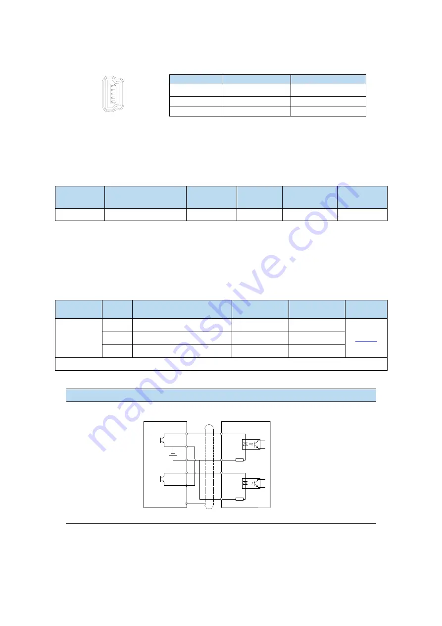
Collector open circuit type (24V voltage) input signal is P+ 24V/D+ 24V
The wiring diagram of P + D, CW, CCW and AB phase interface circuit is as follows:
Open collector (24V voltage)
PLC, CNC and SCM servo driver
Note:
(1) The power supply voltage range of P-/P+ 24V and D-/D+ 24V is 18V~25V. There may be
abnormal pulse and direction if the voltage is lower than 18V.
(2) Servo pulse input port is ON at 10mA.
(3) In order to resist interference, twisted-pair shielding wire must be used.
(4) If the controller is Xinje PLC, the rated current of the pulse output port is 50mA. According to
P-
COM1
COM0
Y0
Y1
+24V
0V
Shield layer
R=3.3K
Ω
P+24V
D-
D+24V
R=3.3K
Ω
Summary of Contents for DS5L1 Series
Page 1: ...DS5L1 series servo driver User manual WUXI XINJE ELECTRIC CO LTD Data No SC5 05 20200929 1 0 ...
Page 2: ......
Page 6: ......
Page 100: ...3 Set the auto tuning interface 4 Click ok to start inertia identification ...
Page 106: ...3 set the auto tuning interface ...
Page 112: ...with higher rigidity 6 Start auto tune 7 Open the servo enable then click ok ...
Page 169: ...Appendix 9 Torque speed characteristic curve ...
Page 170: ......

