Related parameter
Parameter
Meaning
Default
setting
Unit
Setting range
Modify Effective
P5-44
Brake interlock/BK
n.0000
-
n.0000~n.00ff
Anytime
At once
P5-07
Servo OFF delay
time
500
1ms
0
~
65535
Servo bb
At once
P5-08
Brake command
output speed
30
rpm
20
~
10000
Servo bb
At once
P5-09
Brake command wait
time
500
ms
0
~
65535
Servo bb
At once
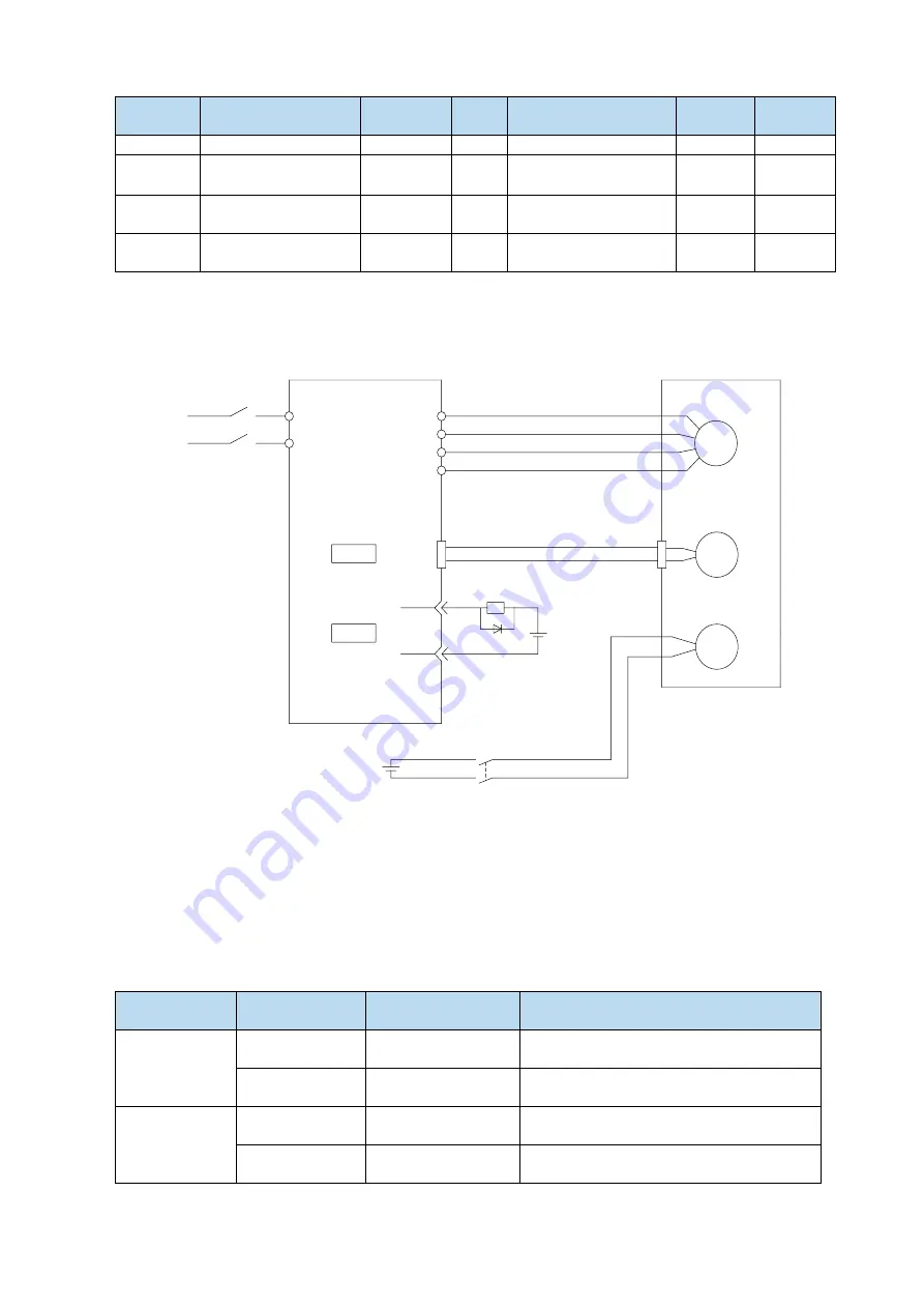
(1) Hardware wiring
The ON/OFF circuit of the brake is composed of the sequential output signal of the servo unit "/BK"
and "brake power supply". A typical connection example is shown below.
M
PG
BK
U
V
W
PE
24V
24V
CN0
SO1
COM
BK-RY
BK-RY
Power
supply
Servo driver
Servo motor
CN2
L
N
Note:
(1) The excitation voltage of the power-off brake is 24V.
(2) If the holding brake current is more than 50mA, please transfer it through the relay to prevent
terminal burnt out due to excessive current.
(2) Software parameter settings
For the servo motor with holding brake, it is necessary to configure one SO terminal of servo driver as
holding brake output /BK function, and determine the effective logic of SO terminal, that is, parameter
P5-44 needs to be set.
Parameter
setting
Servo status
Signal/BK terminal
output logic
Servo motor status
P5-44=n.000□
Servo bb
Invalid
Holding brake power off, motor in position
locked state
Servo run
Valid
The holding brake power is connected and
the motor is in rotatable state
P5-44=n.001□
Servo run
Invalid
Holding brake power off, motor in position
locked state
Servo bb
Valid
The holding brake power is connected and
the motor is in rotatable state
Note:
Summary of Contents for DS5L1 Series
Page 1: ...DS5L1 series servo driver User manual WUXI XINJE ELECTRIC CO LTD Data No SC5 05 20200929 1 0 ...
Page 2: ......
Page 6: ......
Page 100: ...3 Set the auto tuning interface 4 Click ok to start inertia identification ...
Page 106: ...3 set the auto tuning interface ...
Page 112: ...with higher rigidity 6 Start auto tune 7 Open the servo enable then click ok ...
Page 169: ...Appendix 9 Torque speed characteristic curve ...
Page 170: ......


