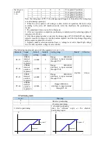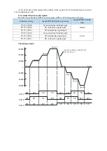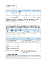
1
:
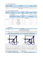
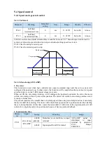
AB
90°
Phase A
Phase B
90°
Phase A
Phase B
2
:
P+D
pulse
direction
ON
pulse
direction
OFF
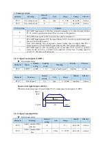
4. Pulse specification
Pulse specification
Highest input
frequency
Voltage
Forward current
Low speed pulse
Differential signal
500Kpps
3.3~5V
<25mA
Open collector
200Kpps
24V
<25mA
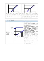
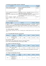
5.3.3 Position control (Internal command)
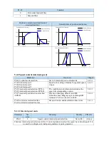
Parameter
Overview
Reference chapter
P0-01 control mode selection
Set to 5: internal position
mode
5.3.3.1
P4-03 internal position mode
P4-04 valid segment number
P4-10~P4-254 internal position 1
to 35 parameters
Control mode setting of
internal
position
mode:
including step change mode,
positioning
mode
and
adjustment time
Configuration
of
pulse
displacement,
speed,
acceleration and deceleration
time of each segment
5.3.3.3
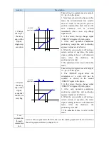
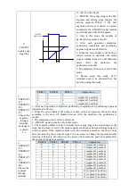
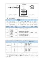
P5-35 change step
signal/GHGSTP
P5-32 pause present segment
signal /INHIBIT
P5-31 jump present segment
signal /Z-CLAMP
Common terminal function
assignment
5.3.3.4
5.3.1.4
5.3.3.5
P4-00 number of Z-phase signal
after leaving limit switch
P4-01 speed of hitting the
proximity switch
P4-02 speed of leaving proximity
switch
P5-28 /SPD-A: find reference
origin on forward side in position
mode
P5-29 /SPD-B: find reference
origin on reverse side in position
mode
Internal position back to
origin setting parameters
5.3.1.8
F2-09 35 segments position
setting
Set
segment
no.
by
communication
5.3.3.6
Summary of Contents for DS5L1 Series
Page 1: ...DS5L1 series servo driver User manual WUXI XINJE ELECTRIC CO LTD Data No SC5 05 20200929 1 0 ...
Page 2: ......
Page 6: ......
Page 100: ...3 Set the auto tuning interface 4 Click ok to start inertia identification ...
Page 106: ...3 set the auto tuning interface ...
Page 112: ...with higher rigidity 6 Start auto tune 7 Open the servo enable then click ok ...
Page 169: ...Appendix 9 Torque speed characteristic curve ...
Page 170: ......


