Parameter
Meaning
Default setting
Range
Change
Effective
P4-04
Effective segment
0
0
~
35
Servo bb
At once
There are 35 sections in total in the internal position. If 10 sections need to be operated and 5 sections
need to be operated switched for use due to process requirements, the effective segment can be set. For
example, parameters are set for sections 1-10, and P4-04 is set to 5, that is, the position of section 1-5 is
valid; if it is set to 10, the position of section 1-10 is valid.
Parameter
Meaning
Default
setting
Unit
Range
Modify
Effective
P4-08
Internal position mode
start segment number
1
-
0
~
35
Servo bb
At once
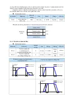
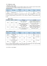
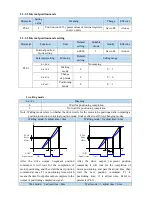
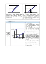
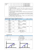
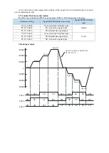
P4-08 sets the starting operation section number after the first round, and it is valid when the
change mode P4-03.1 is set to 0 and 1. The settings are explained below, and valid values are set for
No.1-No.8 sections.
Change
step mode
Setting
Parameter
Actions
P4-03.1=0
P4-08=0 or
P4-08>P4-04
P4-08=8
P4-04=4
start
Segment
1
Segment
2
Segment
3
Segment
4
1≤P4-08≤P4-04
P4-08=2
P4-04=4
Segment
1
Segment
2
Segment
3
Segment
4
start
P4-03.1=1
P4-08=0 or
P4-08>P4-04
P4-08=8
P4-04=4
start
Segment
1
Segment
2
Segment
3
Segment
4
end
1≤P4-08≤P4-04
P4-08=2
P4-04=4
Segment
1
Segment
2
Segment
3
Segment
4
start
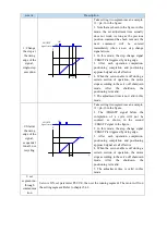
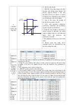
When using skip current segment function, the SI terminal assigned by P5-31 needs rising edge trigger.
5.3.3.4 Change step signal (/CHGSTP)
Parameter
Name
Setting
Meaning
Range
P5-35
Change
step signal
/CHGSTP
n.0000
Defaulted is not distribute to input
terminal. Refer to chapter 5.4.2.
Range:
0000-0014.
Distribute
to
input
terminal through P5-35.
When it set to 0001, it
means input from SI1.
5.3.3.5 Skip present segment signal (/ZCLAMP)
Parameter Signal name
Setting
Meaning
Range
P5-31
Skip the
present
segment
/Z-CLAMP
n.0000
Defaulted is not
distribute to input
terminal.
Range: 0000-0015. Distribute to
input terminal through P5-31. When
it set to 0001, it means input from
SI1.
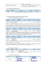
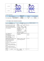
In different Step-Changing modes, the function of skipping the current segment will have different
Summary of Contents for DS5L1 Series
Page 1: ...DS5L1 series servo driver User manual WUXI XINJE ELECTRIC CO LTD Data No SC5 05 20200929 1 0 ...
Page 2: ......
Page 6: ......
Page 100: ...3 Set the auto tuning interface 4 Click ok to start inertia identification ...
Page 106: ...3 set the auto tuning interface ...
Page 112: ...with higher rigidity 6 Start auto tune 7 Open the servo enable then click ok ...
Page 169: ...Appendix 9 Torque speed characteristic curve ...
Page 170: ......


